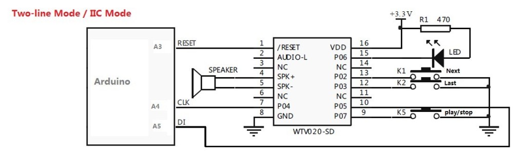
I am trying to get this working and I have a question re: schematic and sketch. In the schematic it is showing only three pins on the arduino used. Pin 1 of the WTV020-SD-16P going to A3 on the Arduino, Pin 7 of the WTV020-SD-16P going to pin A4 of the Arduino, and Pin 10 of the WTV020-SD-16P going to pin 5 of the Arduino.

But in the sketch there are four pins defined. I wired it up as in the schematic but nothing is working.... What am I missing?
int resetPin = 2;  // The pin number of the reset pin.
int clockPin = 3;  // The pin number of the clock pin.
int dataPin = 4;  // The pin number of the data pin.
int busyPin = 5;  // The pin number of the busy pin.
Thanks
Dan