Filtered contact closures for external device over DB15 cable

Hey all,

I am building an Arduino interface to control the tally lights in my studio. I have had success so far, communications between switcher and Arduino are working, LED's light correctly on the test bench. My next step is to send a contact closure over a DB15 cable to a GPIO on my camera controller. That will cause the correct light on the camera to come on as well. Attached is a small diagram of what I am doing. Each output pin has a LED and 220 resistor, when the pin goes high, the LED comes on. I can provide more details as requested.

Any suggestions on the best way to provide a clean contact closure over the DB15 given the outline below?


A completely baffling explanation! Please elaborate!

What do you mean by "contact closure" and how does this need converting and filtering?

What is the "device above" referred to in your picture?

What is going on, what is your project idea about?

Hey Paul,

Sorry to baffle! Let me try again. :slight_smile:

"What do you mean by "contact closure" and how does this need converting and filtering?"

By 'contact closure', I mean closing the circuit like a switch. The diagram in the upper left shows an example of the requirement of the 'device'. BTW that device is a camera controller, it sends signals to the cameras to turn on talent indicator lights.

I think that I need to convert the HIGH voltage signal coming off a pin (I currently use to energize the test indicator LED) and change it to a contact closure that is filtered so no voltage can 'leak' to the other device or damage the Arduino IO pins.

Here is a link to the 'device'... It sounds so ominous being put in ''.... LOL

https://na.panasonic.com/us/audio-video-solutions/broadcast-cinema-pro-video/camera-controllers/aw-rp50-compact-remote-camera

In short, the Arduino is running Firmata

http://firmata.org/wiki/Main_Page

The Arduino receives signals from my switching software over USB/Com3 that will indicate what camera I am using. I can then send that data to my controller via contact closures over a DB15 cable. The controller in turn lights up a big red light on top of the camera. Those are called Tally Lights in general, and the system I am trying to communicate over is called the GPIO, or General Purpose Input Output... The Arduino serves as the bridge between the software and my camera controller. Below is a link to the control software. There is very little documentation. :slight_smile:

https://www.vmix.com/help17/TallyLights.html

I currently have the Arduino running with Firmata, and test LEDs' running off pins 2,4,6,8, and 10 with 220 resistors. I want to keep the test LED's on my final shield layout, but I need to send that same signal to the camera controller as a contact closure. I hope that is a bit easier to understand.

Please let me know if you have any other questions, I appreciate the help.

Your 'links', posted as actual links:

https://na.panasonic.com/us/audio-video-solutions/broadcast-cinema-pro-video/camera-controllers/aw-rp50-compact-remote-camera

http://firmata.org/wiki/Main_Page

https://www.vmix.com/help17/TallyLights.html

Ok, so you need the Arduino outputs to simulate switches connected between the connection to the device and ground. That's easy.

You will need to re-wire your LEDs and series resistors. Instead of wiring them between the Arduino's pin and ground, connect them between 5V and the Arduino pin. You will also need to amend your Arduino sketch. To make a led light, change the pin to output:

pinMode(pin, OUTPUT);

To switch the led off:

pinMode(pin, INPUT);

When set to OUTPUT, the Arduino pin will default to LOW and act like a switch inside the Arduino connecting the pin to ground. When set to INPUT, the Arduino pin will be disconnected from ground, like releasing the switch.

Once you have confirmed that your sketch changes work and your re-wired LEDs behave as before, you can connect the same pins to your device. The voltage output from the device won't damage the Arduino, it is only 3.3V. The 5V from the Arduino will not damage the device because you are not setting the Arduino pin to HIGH. Even if you did that by accident, the diode in the device's opto-isolator would not allow any current to flow in the reverse direction. The current will not damage either the Arduino or the device because of the resistor shown in the device, which is probably a few hundred ohms.

I hope this makes sense. If not, I will draw you a diagram.

Hey Paul,

Thanks, great summary. I follow everything your saying, tonight I will attempt to make the changes and get back to you with my results. I appreciate the advice.

Paul,

So far so no problem on the re-wire, that was direct.

I am having trouble finding where in the code to reverse the state of the pins as signal is sent. I think I see where the default is set in SETUP(), but I get lost after that. Would you suggest I look for help in the Interfacing forum? This may have been been better off there to start... Thanks again.

No, don't start a new thread in another part of the forum on what is essentially the same subject. That's called "cross-posting" and will get you into trouble with the forum moderators. Just post your code here. Use code tags please, rather than attaching the .ino file.

Thanks Paul,

I was hoping this is something someone else has tackled before. I asked a general question to see if anyone knew of a Firmata build similar to what I am looking for, no luck. I will direct any code questions back here if I find anything and won't create any more threads on the subject. I understand very basic coding and circuitry, enough to get me this deep in a project. :slight_smile: After reviewing the code base, it seems rather complex in how it checks and maintains the pin state. I can read part of it, but not enough to follow the more complex logic loops. Thanks again for the help. I keep thinking I find where it goes, but know I am wrong. I can see where ouputPort is setup about 1/4 the way down in FUNCTIONS, but the logic is too complex for me to follow at this time.

I tried to attach the code, but it is too big and I don't know what sections are needed here. I am happy to take it slow and listen to your advice here. This is not something I can do on my own, so I appreciate any support.

I found one block that keeps catching my eye, but I am really not confident that something else in the code also affects things. I have been looking, I am just not experienced enough to find it. Yet... Here it is:

void digitalWriteCallback(byte port, int value)
{
  byte pin, lastPin, mask=1, pinWriteMask=0;

  if (port < TOTAL_PORTS) {
    // create a mask of the pins on this port that are writable.
    lastPin = port*8+8;
    if (lastPin > TOTAL_PINS) lastPin = TOTAL_PINS;
    for (pin=port*8; pin < lastPin; pin++) {
      // do not disturb non-digital pins (eg, Rx & Tx)
      if (IS_PIN_DIGITAL(pin)) {
        // only write to OUTPUT and INPUT (enables pullup)
        // do not touch pins in PWM, ANALOG, SERVO or other modes
        if (pinConfig[pin] == OUTPUT || pinConfig[pin] == INPUT) {
          pinWriteMask |= mask;
          pinState[pin] = ((byte)value & mask) ? 1 : 0;
        }
      }
      mask = mask << 1;
    }
    writePort(port, (byte)value, pinWriteMask);
  }
}

I am beginning to see what you mean. That code is using direct port manipulation. Who knows why, but there it is. Changing that may not be easy or risk free.

I can suggest a simple hardware approach as an alternative, that won't require code changes.

Get yourself a uln2803 chip. They are very common and cheap. Re-wire your leds back to the way they were. Also wire the arduino output pins to the 8 input pins on the uln chip. Then wire the outputs of the uln to the inputs of the device (the dsub connector). Connect the uln's ground pin to the Arduino ground and the ground pin from the dsub connector. No need to connect the "COM(MON)" pin of the uln.

Thanks, that is exactly what I was going to ask next. And thank you on the instructions, I can follow that perfectly.

I am not terribly familiar with this chip, but I was reading on it just before your made this recommendation. I think I follow why I should skip connecting COM on the uln. If I did apply voltage to the COM pin, would the circuit then send the COM supply voltage through the OUTPUT pins when the corresponding INPUT pin went HIGH?

Thanks, and this has been fun. :wink:

Xephius:
If I did apply voltage to the COM pin, would the circuit then send the COM supply voltage through the OUTPUT pins when the corresponding INPUT pin went HIGH?

No, they wouldn't. The ULN's outputs are what is termed "open collector" and cannot source any voltage/current. They can only sink current to ground, or not, like a switch connected to ground. The COM pin is for use with "reactive" loads like motors, relays and solenoids, to prevent the reverse induced voltages those devices can create from damaging the chip. The opto-isolators in your device don't pose such a threat.

PaulRB:
Get yourself a uln2803 chip. They are very common and cheap. Re-wire your LEDs back to the way they were.

Even better, don't use an obsolete IC. Use a TPIC6B595 which has proper FET outputs but you set up with three connections and access using shiftOut. Speed is clearly irrelevant in this case, but like direct port manipulation, this updates all the outputs simultaneously. Since you only need three pins to control it, you are not affecting any pins you do not need to.

The inadequacies of the obsolete uln chip are not really an issue in this circuit, I feel. The currents that need to be switched are small, and the uln's voltage drop won't be an issue when driving opto-isolators, even from a 3.3V source, I'm thinking. But adapting the Firmata code to drive the tpic chip will be at least as difficult as adapting it to use the Arduino output pins directly (which was my previous suggestion), especially for a non-programmer. That's why I suggested the uln chip.

Thank for the advice all around. I will look into the other chip as well, but I did just grab 6 uln chips so I will be getting to know them a little. :slight_smile:

Back on that Paul, would it be more typical to connect the DB15 ground pin to GROUND and the Arduino side to COM? Would that in effect isolate the DB15 from the Arduino? Hope these are appropriate questions here.

I ordered a new protoshield, it has a nice breakout in the center for a chip, I will stick the ULN there and build around it. I also ordered a multi-segment LED bar array, all red, to use as test signal indicators on the shield, a 3ple Decker clear case and a female DB15 connector. Some of it is here, seen below.

I will keep updating this thread as with progress. I am sure I will have more questions as I lay it out.

Also, I was doing some research and found this:

To use relays with Arduino in Tally light you must invert status High with status Low.
To do that in Standard Firmata, you must change the function: writePort(port, (byte)value, pinWriteMask); with this: writePort(port, ((byte)value)^0xFF, pinWriteMask); (the bit are inverted with XOR).

So this might provide more options worth considering, but I wanted to get your thoughts. FWIW, I have an assortment of chips on the way, I don't mind getting more, I am learning a lot and having a good time. Thanks.

IMG_0051.JPG

IMG_0051.JPG

Xephius:
Back on that Paul, would it be more typical to connect the DB15 ground pin to GROUND and the Arduino side to COM? Would that in effect isolate the DB15 from the Arduino? Hope these are appropriate questions here.

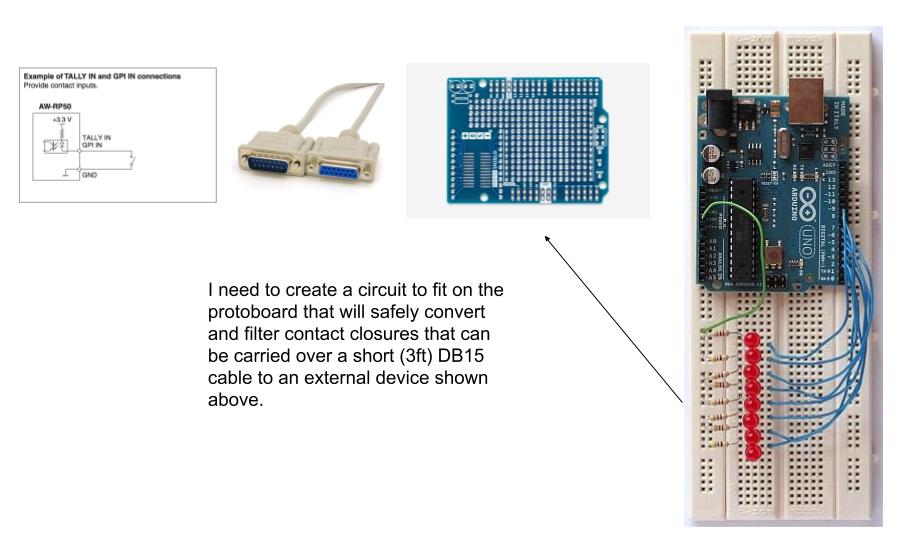
Sorry, that is not making much sense. We seriously need a proper diagram of how you intend to use the "DB15 cable" to connect your tally lights. Using either a ULN chip or a TPIC6B595 will provide good isolation from the Arduino - if wired properly.

Xephius:
To use relays with Arduino in Tally light you must invert status High with status Low.
To do that in Standard Firmata, you must change the function: writePort(port, (byte)value, pinWriteMask); with this: writePort(port, ((byte)value)^0xFF, pinWriteMask); (the bit are inverted with XOR).

That would be one way to do it, but there probably is a "bit invert" function in the language as well to the same effect.

There is a lot of confusion here. You are posting "snippets". The peculiar code to which PaulRB commented

PaulRB:
I am beginning to see what you mean. That code is using direct port manipulation. Who knows why, but there it is. Changing that may not be easy or risk free.

... indicates nothing more than a clumsy, almost certainly automated translation from the Firmata code you just cited. It is not difficult to do it properly and we are prepared to assist (well, I am!) but as always, we need the actual code to work with. Please either post it all here, or at the very least cite the source URL - I cannot readily find it among the links you have offered so far.

Not didactically cited, but part of the necessary explanation, I presume the "interface" from which you are controlling this is a PC to which the Arduino is connected by USB. As such we can be reassured that there are no other encumbrances on the Arduino at this point (that is, nothing else to be connected or controlled) so that PaulRB's concern about "risk free" is moot and the actual code can be massively cleaned up from the Firmata kludge.


Oh, and a final observation:

As I am prone to mention, the UNO and its shields are in general, more of a "demonstration" system than practical. Your final version would be more robust using a Nano and the interface chip mounted on a soldered perfboard.

If Firmata worked via WiFi, you could use these modules with ESP-01s at each tally light location and avoid the cabling.

would it be more typical to connect the DB15 ground pin to GROUND and the Arduino side to COM?

No, that would prevent it from working at all! If you connected COM like that, it would appear to your video device that all the contacts are closed all the time. Just leave COM unconnected.

To use relays with Arduino in Tally light you must invert status High with status Low.
To do that in Standard Firmata, you must change the function: writePort(port, (byte)value, pinWriteMask); with this: writePort(port, ((byte)value)^0xFF, pinWriteMask); (the bit are inverted with XOR).

That is exactly the code changes we were considering before but decided were too difficult/risky. But the author has given the solution. So you can go back to plan A, no ULN chip needed.

Thanks for the updates all around.

I will work on a wire diagram to share here. I am still learning the tools available to do some of this, I will get it up ASAP. Also, thanks for turning me onto the transistor arrays, those will be good to learn about. I will do some separate tutorials.

Point taken on the protoboards and Uno not being ready for production. Once I finish the design, I will learn how to convert it all to a Nano on an etched board. Very excited to learn this.

I like the idea of using those modules, but for now the camera controller has the tally lights and that is why I am going through all this trouble. I will look into those soon for other ideas. And as to the code clean up, I agree. Once I have a proof of concept working, I would love to take a stab at that with some guidance.

It seems like the next best step is for me to do a schematic of my design. Is there a software package or website you would suggest I use to do that? I appreciate the advices as always.

Schematic editors or PCB design packages (which almost always include a schematic editor)? Are you intending to etch at home? Having a PCB manufactured in China is amazingly cheap these days, probably on a par with buying all the materials and equipment for home etching, ignoring your time and effort on top of that.

The simplest schematic editor to learn, and the quickest to produce a simple schematic is... pencil & paper.

After that, there are regular discussions on the subject on this forum. Use the forum Search to find them. The three I have used are Fritzing (easier to learn, bad reputation on this forum because beginners use the "breadboard view" and call that a schematic, which winds up many forum members, and the parts library is not extensive); Eagle (more difficult to learn, extensive parts library); easyEDA (web-based and linked to a PCB fabrication service). I have used esayEDA to design boards but not had any manufactured yet.

Hey Paul,

I tried to use easyEDA, worked well I think. I will definitely use it again, and I will see about ordering a board through the service and see how it turns out. I have etched in the past, and probably will again in the future, but I would happily paid for a fast production, production ready board. :slight_smile:

Here is my schematic, if you think it will work, I can start laying it out to test.