Hello guys, newbie here. Just started my project and it's about the subject name . I'm currently waiting for my arduino to arrive so i'm using Proteus to simulate the whole circuit + arduino. I also tried learning some basic arduino stuff ,i think i'm close but i have no results yet. Anyone willing to help?? I posted circuit below .


Hi geoland,
Although you may think the title and attachments are enough, we’ll need more detail.
What exactly are you looking for? Someone to look over your sketch or someone to write it from scratch?
You’ll get more quality responses if you reply with some specifics.
Thanks!
Pat.
I need someone to look over my scetch and code, I just want a little push so i can do it by myself. I want to know if there are any mistakes in the circuit and if there is a way to check the code i wrote as for now i cannot figure out some things
You can see from images on oscilloscope that Vpeak in A0,A1,A2 is 1,2v ,so knowing that arduino max is 5V =1023, our max is 246
Here is the code:
#include <LiquidCrystal.h>
const int rs = 12, en = 11, d4 = 5, d5 = 4, d6 = 3, d7 = 2;
LiquidCrystal lcd(rs, en, d4, d5, d6, d7);
void setup() {
pinMode(A0,INPUT);
pinMode(A1,INPUT);
pinMode(A2,INPUT);
// put your setup code here, to run once:
}
void loop() {
// put your main code here, to run repeatedly:
double r=analogRead(A0);
double y=analogRead(A1);
double b=analogRead(A2);
if (r>130 && r<250)
{
delay(6.66666);
if (y>130 && r<250)
{
lcd.print("RIGHT");
}
if (b>130 && b<=250)
{
lcd.print("LEFT");
}
}
}
This is from my first projects in arduino, Hope you Understand ![]()
Review "delay()". Takes an integer, not a float.
Paul
Good point, but it’s not technically wrong because the compiler will cast it, but delay() is in ms, not seconds. Do you mean 6666 for 6.666 seconds?
analogRead() returns an int in range 0-1023, not a double or float.
Change your voltage divider to go a little lower, peaks at about 1V, and use the internal 1.1V reference for better ADC stability.
I reduce R1 to 50K so now the vout=12*(R2/(R1+R2)) = 2 volt,in proteus voltmeter i see 1.7 Volt ,the voltage after diode is 0.6 volt and Vpeak= 0.6/0.707=0.84. So if the 5V=1023 then 0.84V =172 , so the values in each analogInput should be 0-->172. I'm ok till here, but something is missing, The lcd doesnt display a value at all
After you deal with your LCD issues, remember you need to sample the voltage fast enough to satisfy the Nyquist limit. i.e., if it's a 60Hz waveform, sample at least at 120Hz, preferably faster. The problem is that the LCD display code is probably fairly slow, so you won't be able to sample and update the LCD in one loop fast enough.
The lcd doesnt display a value at all
Have you ever seen the LCD print anything? If not, then I suggest you start with a simple "Hello World" example sketch to make sure your wiring is correct.
Maybe your detection circuitry is ok now, but the LCD isn't.
Also - what did you ever do with the delay and analogRead statements? Can you post your new code?
Pat.
yeah the lcd dislays but not the correct value,sorry for the misunderstanding. for example when i try read a value from a potentiometer in A0 it shows only one value, the circuit remains the same as from the picture ,removed the wires from A0,A1,A2 and installed a potentiometer in A0 ,check the code:
#include <LiquidCrystal.h>
LiquidCrystal lcd (12,11,5,4,3,2);
int pot=A0;
void setup() {
// put your setup code here, to run once:
pinMode(pot,INPUT);
lcd.begin(16,2);
}
void loop() {
// put your main code here, to run repeatedly:
int value=analogRead(pot);
if(value>512)
{
lcd.print("Over 2.5");
}
if(value<=512)
{
lcd.print("under 2.5");
}
delay(10000);
}
the lcd displays only Over 2.5, even if the A0 is grounded
thank in advance
Start printing the analogRead() results to the display or the Serial monitor. That shows you what is actually read.
You may also want to consider shortening the delay to 1000 during testing. 10 seconds is a long time to wait...
Try removing this line:
pinMode(pot,INPUT);
I know that setting the mode to INPUT_PULLUP will definitely cause the problem you're seeing, maybe this will also.
cedarlakeinstruments:
Try removing this line:
pinMode(pot,INPUT);I know that setting the mode to INPUT_PULLUP will definitely cause the problem you're seeing, maybe this will also.
Just remove the line?? Yeah it works now ![]() I also changed the arduino in proteus
I also changed the arduino in proteus ![]() Thank you guys, i'll post updates
Thank you guys, i'll post updates
When i try with the DC source it displays the number correct, but if i connect the A0 to the rectifier it displays always '0'. Check the attachments below


Take another look at my post #7 and see if it applies...
geoland:
When i try with the DC source it displays the number correct, but if i connect the A0 to the rectifier it displays always '0'. Check the attachments below
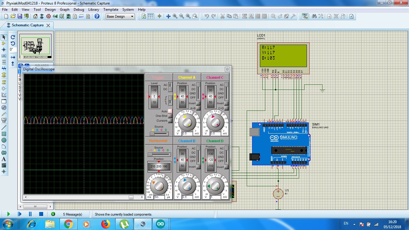
I think i'm close now, please check attachments, The R and B values are the maximum values read in A0 and A1(Or at least i hope), B are the instant readings in A1. So the next step is to compare the readings in A0,A1 and A2. As we know each phase seperation in 3 phase system is 120°, So in 50Hz the period is 20ms, so the difference of the each phase is 6.66666 ms . As you in attachment the max value(V peak) is 117-118 ,about 0.55 volt. So i must compare the value of A0 with the value of A1 after 6.6666ms, if they are about the same then the sequence is RIGHT,else if the value of A0 equals the value of A2 after 6.6666ms then the sequence is LEFT. Another thing i have to figure out is, for the system to work with different Hz, for example with 60Hz 3phase systems without need to change the code. So i need the code to check the period and then proceed to the rest. Till now i successfully display the readings in A0,A1,A2,here is the code:
#include <LiquidCrystal.h>
LiquidCrystal lcd (12,11,5,4,3,2);
int max1=0,max2=0;
void setup() {
// put your setup code here, to run once:
lcd.begin(16,4);
}
void loop() {
// put your main code here, to run repeatedly:
lcd.setCursor(0,1);
int value=analogRead(A0);
int value1=analogRead(A1);
int value2=analogRead(A2);
for (int i=0;i<250;i++)
{
if (value>max1)
{
max1=value;
}
}
for (int r=0;r<250;r++)
{
if(value1>max2)
{
max2=value1;
}
}
lcd.setCursor(0,0);
lcd.print("R:");
lcd.print(max1);
lcd.setCursor(0,1);
lcd.print("Y:");
lcd.print(max2);
lcd.setCursor(0,2);
lcd.print("B:");
lcd.print(value2);
}

If I understand this project, you are trying to understand the order of phasing of a three-phase signal. Wouldn't it be much simpler to record the zero crossings of each channel, so you don't have to worry about speed of analog acquisition or signal amplitude?
Yeah it sounds like a good idea.Can you give me an example??
should i check it using something like this??
while (r==0)
{
mark1=millis();
}
while (y==0)
{
mark2=millis();
}
while (b==0);
{
mark3=millis();
}
if (mark1<mark2 && mark2<mark3)
{
lcd.print("RIGHT");
}
else
lcd.print("left");
That code contains three infinite loops.
Why don't you describe in detail in words and images what you actually try to accomplish (and use code tags when posting code).