Are Four 74HC595 Sift-registers in a row too many?

Hi,

I am trying to control 32 solenoids through four shift registers (74HC595 plus one Tip120 for every solenoid). Therefor I started using the example for two shiftregister by Tom Igoe

It also works super fine for two shift registers, I only modified it a bit in order to control them individually through the serial.read() function:

void loop() {
 
  if (Serial.available() > 0) {
    int thisLed = Serial.read()-48;
    
    registerWrite(thisLed, HIGH);
    delay(500);
    // if this is not the first LED, turn off the previous LED:
    if (thisLed > 0) {
      registerWrite(thisLed - 1, LOW);
    } 
    // if this is  the first LED, turn off the highest LED:
    else {
      registerWrite(31, LOW);
    } 
    // pause between LEDs:
    delay(250);
  }

}

NOW the problem is as soon as I attach four shift registers it seems that it works still fine with the first two, but instead of controlling the two following separately they also go off when the first two are addressed. As if mirrored...

Meaning when I address the first pin of the first shift-register the signal also goes to the first pin of the third shift register.
I open the Serial Monitor and input from "0" to "7" in order to address the first 8 outputs of the shift-register (Hope this makes sense?) the "8" to "?" for the next 8 following the asciitable:

The same happens with the others (when the first pin of the second register is addressed, the solenoid attached shoots once and at the same time the one attached to the first pin of the fourth register starts to go off in a frequent way)

THANKS for any suggestions to this issue.

Best,
PJ
So where's the rest of your code? Does your apparently proprietary code clear the whole chain?

And btw. did you add that infamous capacitor on the latch line? With that respect the tutorial is simply wrong. It's been that way for ages...

Hi,

the rest of the code is still the same as in the tutorial, I just posted the little change I made:

/*
  Shift Register Example
 for two 74HC595 shift registers

 This sketch turns on each of the LEDs attached to two 74HC595 shift registers,
 in sequence from output 0 to output 15.

 Hardware:
 * 2 74HC595 shift register attached to pins 2, 3, and 4 of the Arduino,
 as detailed below.
 * LEDs attached to each of the outputs of the shift register

 Created 22 May 2009
 Modified 23 Mar 2010
 by Tom Igoe

 */

//Pin connected to latch pin (ST_CP) of 74HC595
const int latchPin = 8;
//Pin connected to clock pin (SH_CP) of 74HC595
const int clockPin = 12;
////Pin connected to Data in (DS) of 74HC595
const int dataPin = 11;

char inputString[2];

void setup() {
  //set pins to output because they are addressed in the main loop
  pinMode(latchPin, OUTPUT);
  pinMode(dataPin, OUTPUT);  
  pinMode(clockPin, OUTPUT);
  Serial.begin(9600);
  Serial.println("reset");
}

void loop() {
  // iterate over the 16 outputs of the two shift registers
//  for (int thisLed = 0; thisLed < 16; thisLed++) {
    // write data to the shift registers:
  if (Serial.available() > 0) {
    int thisLed = Serial.read()-48;
    //Serial.println(thisLed);
    
    registerWrite(thisLed, HIGH);
    delay(500);
    // if this is not the first LED, turn off the previous LED:
    if (thisLed > 0) {
      registerWrite(thisLed - 1, LOW);
    } 
    // if this is  the first LED, turn off the highest LED:
    else {
      registerWrite(31, LOW);
    } 
    // pause between LEDs:
    delay(250);
  }

}

// This method sends bits to the shift registers:

void registerWrite(int whichPin, int whichState) {
  // the bits you want to send. Use an unsigned int,
  // so you can use all 16 bits:
  unsigned int bitsToSend = 0;    

  // turn off the output so the pins don't light up
  // while you're shifting bits:
  digitalWrite(latchPin, LOW);

  // turn on the next highest bit in bitsToSend:
  bitWrite(bitsToSend, whichPin, whichState);

  // break the bits into two bytes, one for 
  // the first register and one for the second:
  byte registerOne = highByte(bitsToSend);
  byte registerTwo = lowByte(bitsToSend);

  // shift the bytes out:
  shiftOut(dataPin, clockPin, MSBFIRST, registerTwo);
  shiftOut(dataPin, clockPin, MSBFIRST, registerOne);

  // turn on the output so the LEDs can light up:
  digitalWrite(latchPin, HIGH);
}

I didn't add the capacitor since I read on another post that it could supposedly damage the arduino... then I didn't put it anywhere.
Should it go between Pin 16 (Vcc) of the shift-register and ground of the arduino?

Best,
PJ

You need capacitors when you drive 4 registers,
and also you need capacitors because of the solenoids.

If you don't use capacitors, there are spikes for some nanoseconds,
where the supply to the registers will drop down.

I use one 47uF Tanatalum for a matrix 7x17 LEDs, I think it has 6 registers.
If you use electrolytic higher capacity is required or low ESR is required.

You can use many shift registers, if you have 2 and another 2,
after 4 cycles, the last two will have the same content as the first two.

Means for 4 cycles you need to send 4 different bytes.

Your program seems to have logic errors! I looked and as far as I understand, you send the bitstream each time. and why do you wrap 2 8 bit writes into one 16 bit write?

What you need to do:

Prepare the data you want to send into 4x8 bits.
Send the data once, 4x 8 bits.

To make it easier at first test with dummy values (as it looks you read the data from a serial port).

I also think you're better off writing your own code.

The registerWrite() function only deals with a 16-bit wide variable. If you instruct it to set pin #31 in a chain of 4 shift registers it simply must fail !

As suggested before, do your own data preparation. Then you know what it is doing. When you have all 4 bytes ready, simply send all of them out. The code you use to set up the data-bytes should be aware of the number of shift registers it has to deal with.

takao21106:
You need capacitors when you drive 4 registers,
and also you need capacitors because of the solenoids.

ok, i got that. So you would suggest to use 4 capacitors (0.1uF?), one for each shift-register? Put between the Vcc of the register and arduino ground?

PaulJakob:

takao21106:
You need capacitors when you drive 4 registers,
and also you need capacitors because of the solenoids.

ok, i got that. So you would suggest to use 4 capacitors (0.1uF?), one for each shift-register? Put between the Vcc of the register and arduino ground?

1 capacitor is enough for the 4 registers together I would not say it has to be 0.1 uF.
Use whatever you have around, apply common sense, experiment.
0.01uF might be enough, where 470uF also won't do damage.
Some types/brands also don't work right for some purposes.

Show a photo of the solenoids + TIP120 and then I can tell you if you need more capacitors.

If you use low frequency you can get away without 0.1 capacitors eventually but you have to verify that for each individual circuit.

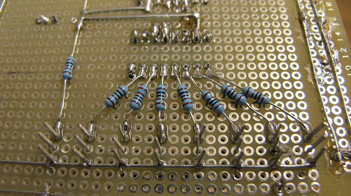
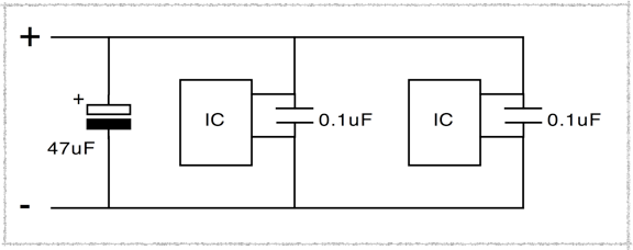
On the top is the Capacitor 47uF, where the 5V from the arduino comes and the ground is. I made it pretty much like described here:

The there are the 32 tip120s for the solenoids. The second image shows the soldering from the shift register to the tip120s.

There is one big capacitor already on the board!

Have you changed the program so it works? I don't think the code you show can work correctly at all.

At max. I would add 2 capacitors, one each for two register chips.
The value does not really matter. It's just buffering/decoupling.

For instance I use one small 1uF capacitor for 5 chips together, one PIC, 3 shifting register,
one LED display, works fine.

If you already have one 47uF somewhere, you don't neccessarily need another big 47uF capacitor.

But these buffering/decoupling capacitors are required. I saw it when I built this 7x17 matrix, without capacitor, only one half of the LED would update, and it was sensible to touching of the PCB.

Decoupling capacitors become more important when you use more MHz, and nanoseconds timing.
And you also need them when you switch high currents.
If you have many available, don't have to save on capacitors, and have board space available, add as many as you like or you think make any sense.

I also highly doubt you can switch on 32 Solenoids at once, using the Arduino 5 volts. I would even question if it is enough for 2 or 3 solenoids.

There is one rule that says add at least 1000uF/Ampere. It really depends if you have a 50Hz wall adapter, or a switching regulator (they do not need that much capacity).

thanks, the solenoids run on 18v which comes from a power supply.

dou have any idea on how to send the right bits to the registers. i am a bit confused quiet frankly...

Electrical Engineer says: put a 0.1uF cap from every Vcc pin to gnd.
Use SPI to down the 4 bytes into the shift registers.

digitalWrite (SS, LOW); // SS goes to the SRCK line
SPI.transfer (shiftRegister1data); // SCK goes to RCK pin, MOSI goes to Serial Data pin
SPI.transfer (shiftRegister2data);
SPI.transfer (shiftRegister3data);
SPI.transfer (shiftRegister4data);
digitalWrite (SS, HIGH); // all outputs are updated when SS goes high.

spend the rest of your time in void loop deciding on the order you want things to turn on or off.

thanks sir, so i did :slight_smile:
thanks for the code, i'll start the software now.

ok, one question regarding your code:

At the moment I have it like this:

Datapin (Arduino: 11) -> goes to SI (14) pin of the 74HC595
Clockpin (Arduino: 12) -> goes to SCK (11) pin of the 74HC595
Latchpin (Arduino: 8 ) -> goes to RCK (12) pin of the 74HC595

NOW, it says in your code in the comments that "SCK goes to RCK pin, MOSI goes to Serial Data pin" what does this exactly mean? I mean, which arduino pin do I connect with which of the registers pins?

Thanks!

This display ?
http://www.youtu.be/OW8FVmrA7js
has 9 '595s daisy-chained.
The display has 70 pixels, the 595s have 72 outputs total, so I have to knock out two dummy bits at the end to push everything through.

runaway_pancake:
This display ?
http://www.youtu.be/OW8FVmrA7js
has 9 '595s daisy-chained.
The display has 70 pixels, the 595s have 72 outputs total, so I have to knock out two dummy bits at the end to push everything through.

Hey, that looks super cool!

I don't really get the dummy bit part? Could you share some of your code for me in order to understand? I'm a bit stuck with the transfer part...how do I address one specific pin of one of the 4 registers and shut up all the others?

Cheers!

Let's deal with one, first.
Let's say you sent out bits to turn on #1. You clock out 0000 0001.
Later you want to turn #5 on and leave #1 on. You clock out 0001 0001.
Later you want to turn off #1 and leave #5 on. You clock out 0001 0000.
Finally, you want to turn on #4 and #6 and everything else off. You clock out 00101000
You have to send/re-send the whole stream each time. See?

thanks , sounds clear. i'll try it later and'll get back to you as it works.

These are the SPI pins:
MOSI: (Master Out Slave In) Datapin (Arduino: 11) -> goes to SI (14) pin of the 74HC595
SCK: Clockpin (Arduino: 13) -> goes to SCK (11) pin of the 74HC595
SS: Slave Select (Arduino: 10 ) -> goes to RCK (12) pin of the 74HC595

You will need this at the top of your sketch
#include <SPI.h>
byte SS = 10;

and this within void setup()
pinMode (SS, OUTPUT);
SPI.begin();

Hi Guys,

sorry but I really don't get something fundamental here. So I was trying with basically just entering "0000 0001" to SPI.transfer(); to see if that works, it didn't.
Then I tried some others and e.g. the code below sometimes shoots of the first, sometimes the 9th, sometimes the 25th....even though it shouldn't even start the function, should it?
What do I not get here?

Thanks...

#include <SPI.h>

int ss = 10;

void setup() {

  pinMode (ss, OUTPUT);
  SPI.begin();
//  SPI.setBitOrder(MSBFIRST);
  
}

void loop(){
  for(int i = 0; i < 0; i++){
    sendToRegister(0);
    delay(2000);
  }
}

int sendToRegister(int valueForSolenoid) {

  digitalWrite(ss,LOW);
  SPI.transfer(valueForSolenoid);
  digitalWrite(ss,HIGH); 
  
}

ok, another approach, again with shiftOut(); which doesn't work at all...
(I modified the code I found here: http://www.makeuseof.com/tag/arduino-programming-playing-shift-registers-aka-leds/ )

int data = 11; // where we send the bits to control outputs 
int clock = 12; // keeps the data in sync
int latch = 8; // tells the shift register when to activate the output sequence
 
void setup()
{
   // set the three control pins to output
  pinMode(data, OUTPUT);
  pinMode(clock, OUTPUT);  
  pinMode(latch, OUTPUT);  
 
  Serial.begin(9600);

}
 
void loop(){ 

outputBytes(2,1); // just to have some values which later can be addressed dynamically from  Processing
    
}
 
 
void outputBytes(int whichRegister, int whichPin){
  
    // start to set every output to 0
    byte dataValues1 = B00000000;
    byte dataValues2 = B00000000;
    byte dataValues3 = B00000000;
    byte dataValues4 = B00000000;
   

    if(whichRegister == 1){
      dataValues1 = B00000001; // set to first pin of the register
      dataValues1 = dataValues1 << whichPin; // move to the actual pin
    }else if(whichRegister == 2){
      dataValues1 = B00000001;
      dataValues2 = dataValues2 << whichPin;
    }else if(whichRegister == 3){
      dataValues3 = B00000001;
      dataValues3 = dataValues3 << whichPin;
    }else if(whichRegister == 4){
      dataValues4 = B00000001;
      dataValues4 = dataValues4 << whichPin;
    }
    

      // go through the registers and address the one chosen pin, set all other pins to 0 (no output)

      digitalWrite(latch, LOW);     

      shiftOut(data, clock, MSBFIRST, dataValues1); 
      shiftOut(data, clock, MSBFIRST, dataValues2); 
      shiftOut(data, clock, MSBFIRST, dataValues3); 
      shiftOut(data, clock, MSBFIRST, dataValues4); 

      digitalWrite(latch, HIGH);   
 
       
       delay(1000); 


       // set everything back to 0

       dataValues1 = B00000000;
       dataValues2 = B00000000;
       dataValues3 = B00000000;
       dataValues4 = B00000000;

       digitalWrite(latch, LOW);     

      shiftOut(data, clock, MSBFIRST, dataValues1); 
      shiftOut(data, clock, MSBFIRST, dataValues2); 
      shiftOut(data, clock, MSBFIRST, dataValues3); 
      shiftOut(data, clock, MSBFIRST, dataValues4); 

       digitalWrite(latch, HIGH); 
       
       delay(1000); */
 
}

this doesn't work like this, though it seems to work when I just go through the pins using a for() loop:

void outputBytes(){
 
    byte dataValues = B00000001; // change this to adjust the starting pattern
 
 
    for (int i=0;i<8;i++){
      digitalWrite(latch, LOW);     
      Serial.println(dataValues, BIN);  // Debug, sending output to the serial monitor
      shiftOut(data, clock, MSBFIRST, dataValues); 
      digitalWrite(latch, HIGH);   
      dataValues = dataValues << 1; // Shift the bits one place to the left -  change to >> to adjust direction
      delay(100);    
    }
 
}

What am I not getting?

Is it also stupid of me to just attach 8 LEDs (instead of solenoids at the moment) to one register and then move them to the others to test one register at the time while there are no LEDs connected to the other registers?
I mean is it necessary to connect all 32 LEDs (solenoids) to the 32 outputs of the registers in order to get the code working right?

Cheers!