Thanks for the capacitor tip. I tried it out and here are the results.
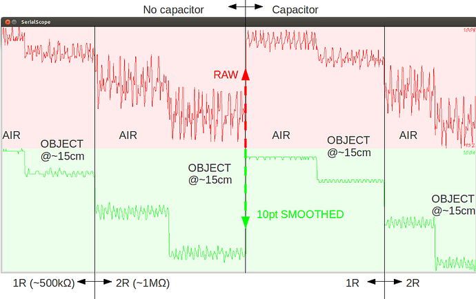
Three emitting LEDs were always on, drawing around 30mA each, placed around the receiver. The ADC was sampling the receiver and dumping out the raw signal (red) and the 5 point average (green).
I tried to guesstimate what happens at the far limit of detection, around 15 cm (closer than 10cm it's ridiculously easy). The AIR refers to nothing above the receiver. The OBJECT@~15cm refers to a chunk of veroboard placed roughly 15cm above the receiver. I tried increasing the overall resistance to see how far I could push the ADC (and hopefully, the detection). As it turns outthe ADC was surprisingly cooperative. The 1R / 2R refer to one or two series resistors of about 500k? before the receiver. The No Capacitor / Capacitor refers to having a round ceramic cap (561 J | B1 (I think) 64, whatever that means, I don't have another one I 'm afraid) attached between GND and the analog pin as suggested.
Looking at the top (red) window, it is not very apparent if the cap helps, but perhaps it's not an adequate cap. However, software smoothing does quite a neat job. As for detection, the 2R case yields a slightly bigger difference, but nothing to write home about. We are looking at a very tiny range, 1008-952 (ADC units) at the top window and 1004-961 at the bottom. Still, interesting results, I hadn't played with IR before.
By the way, I have no idea what kind of beam my IR LEDs have, but by a very rough approximation, looking at the size of the visible spot they make against an object when seen through a digital camera I 'd say they have a cone of ~60 degrees (give or take a hundred :~).
