/* This sketch detects analog signals from the potentiometers ud and lr
and sends them to the serial monitor.Pixels on led matrix are selected or deselected by buttons a and b */
//initialize variable for x and y values on the potentiometers and the pushbuttons at digital pin 4 and 7
int UD;
int LR ;
int button_a = 4;
int button_b = 7;
bool stored_state [16][16];
int last_x, last_y;
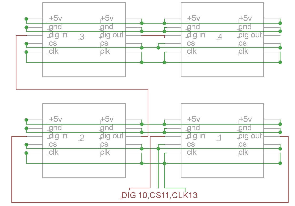
#include "LedControl.h" // importing the library
// DIN to 10, CLK to 12, CS to 11
LedControl lc = LedControl(11, 13, 10, 4);
void setup() {
Serial.begin(9600);
lc.shutdown(0, false); // turn off power saving, enables display
lc.setIntensity(0, 0); // sets brightness (0~15 possible values)
lc.clearDisplay(0);// clear screen
lc.shutdown(1, false); // turn off power saving, enables display
lc.setIntensity(1, 0); // sets brightness (0~15 possible values)
lc.clearDisplay(1);// clear screen
lc.shutdown(2, false); // turn off power saving, enables display
lc.setIntensity(2, 0); // sets brightness (0~15 possible values)
lc.clearDisplay(2);// clear screen
lc.shutdown(3, false); // turn off power saving, enables display
lc.setIntensity(3, 0); // sets brightness (0~15 possible values)
lc.clearDisplay(3);// clear screen
pinMode(button_a, INPUT); // button is input
digitalWrite(button_a, HIGH); // initalize button as ON
pinMode(button_b, INPUT); // button is input
digitalWrite(button_b, HIGH); // initalize button as ON
}
void loop() {
UD = analogRead(A1); // read analog value at pin A1 and stores as UD
LR = analogRead(A0); // read analog value at pin A0 and stores as LR
int stateA = digitalRead(button_a); //determines the state of button_a (HIGH or LOW)
int stateB = digitalRead(button_b); //determines the state of button_b (HIGH or LOW)
// scales down the value from 0-1023 to 0-15
char x_translate = map(LR, 0, 1023, 15, 0);
char y_translate = map(UD, 0, 1023, 0, 15);
if ( (last_x != x_translate) || (last_y != y_translate) )
{
// the position has moved so we need to restore previous state
lc.setLed(0, last_x, last_y, stored_state [last_x][last_y] );
lc.setLed(1, last_x, last_y, stored_state [last_x][last_y] );
lc.setLed(2, last_x, last_y, stored_state [last_x][last_y] );
lc.setLed(3, last_x, last_y, stored_state [last_x][last_y] );
}
last_x = x_translate;
last_y = y_translate;
Serial.print ("Button_a=");
Serial.print(stateA, DEC);
Serial.print ("Button_b=");
Serial.print(stateB, DEC);
Serial.print(", UD = ");
Serial.print(UD, DEC);
Serial.print(", LR = ");
Serial.print(LR, DEC);
Serial.print(", x = ");
Serial.print(x_translate, DEC);
Serial.print(", y = ");
Serial.println(y_translate, DEC);
// clears display whenever a new value is updated
/// --> dont do this! lc.clearDisplay(0);
// just set led in new potentiometers position
lc.setLed(0, x_translate, y_translate, true);
lc.setLed(1, x_translate, y_translate, true);
lc.setLed(2, x_translate, y_translate, true);
lc.setLed(3, x_translate, y_translate, true);
// if button_a is pressed, store it
if (stateA == 1) {
stored_state [last_x][last_y] = true;
}
// if button_b is pressed, delete it
if (stateB == 1) {
stored_state [last_x][last_y] = false;
}
delay(150); //Mess with delay to tweak accuracy
}
Hi
I'm using this code to control 4 8x8 led matrix(Max7219) and the idea is to use two potentiometers to control left,right,up and down of the cursor and two buttons for on and off of the selected led.
This works fine but I have the same display repeated on all 4 matrices rather than one big matrix.
Any help or advice greatly appreciated
Rich