Hi everyone,
I know next to nothing about electronics, but I'm a programmer.
I found this tutorial for an Ambilight and followed the hardware part since it's pretty much as simple as can be - power supply, LED strip, Arudino, PC, connect them all directly.
For the software part I used more or less the sketch from the tutorial, with one probably important note; I increased the baud rate and for the PC side I wrote an app from scratch to get the colors from my screen, do some calculations and send them on to the Arduino.
This setup has been working great for almost a year now (although about a couple months ago I enclosed the Arduino in a plastic case finally which, while not terribly claustrophobic, it might have gotten in the way of airflow from the jumper cable a little bit).
Yesterday, however, I noticed a smell... Of burning plastic... So I finally realised it's coming from the Arduino and noticed that the square bit (connector) of the jumper cable going into the ground pin on the Arduino has started to melt. I quickly unpluged everything.
Now, since I know next to nothing about electronics, I don't really know what to do to:
a) figure out what the problem is and
b) fix it
Now, obviously something is working too hard and causing a lot of heat, but for all I know, it might be normal for 5V 10A going through a standard jumper cable (which is quite tiny, but not sure how I would get a thicker cable into the Arduinos ground) to get so heated...
But regardless of whether it's normal or not, I need your help to either know that it's normal in which case I'll try to implement some cooling solution or in the more likely case that something's wrong figure out what... Is it the power supply giving out? The LED strip has a short circuit? ...
Whatever it is, I need help diagnosing it. I do have a multimeter and know how to use it (in the sense that I know to put the two things on two areas and then turn to the right dial to get a V/A/Ohm measurement), but I don't know what to do with it, mostly because I don't know what to look for (e.g. PSU is 5V 10A, but if I get slightly over/under those figures I don't know if that's still ok or not and such).
Can anybody help me diagnose this? Thanks in advance!
P.S. I didn't attach photos or sketches or anything because I'm not sure anything is needed, but as an idiot playing with something beyond his ken I am at your service for ridiculing me and asking me for whatever you need to make it easier to help me
There should never be 10 amps flowing in the Arduinos ground, that current only exists betwwen the led strips and the power supply.
As for the makeuseof article, I cannot find a schematic or anything other than text. Is there diagram somewhere showing you how to connect things? I sure don't see it.
It would probably be best if you post some photos of how this are wiring, otherwise we can only guess as to the source of the problem(s).
There's actually a disclaimer in the article with that:
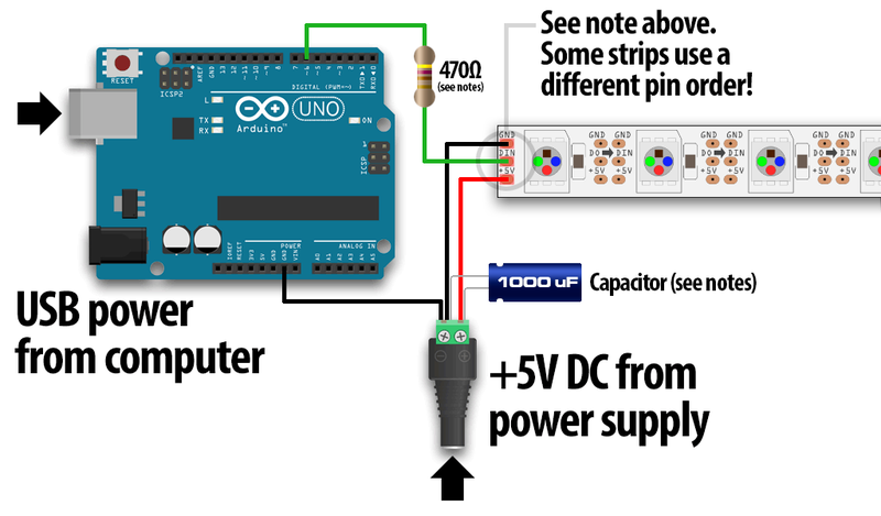
Do not attempt to provide power to the strip by the 5V pin on the Arduino. You will fry the Arduino, very quickly. Instead, use an external 5V power supply.
There's no diagram because all the wiring is is:
Connect pin 6 from the Arduino to the DIN on the LED strip – your strip should have a breakout lead on one end, so use a male-female jumper wire. Also connect the GND pin from the Arduino to GND on the strip.
Which is what I did, except instead of using a male-female jumper wire I used a male male, cut off one end and solder the wire to the wire from the strip connector.
The strip connector has one wire connected to the DIN of the strip and the other wire connected to the GND on the strip and the jumper cables are in my Arduino on GND and pin 6.
The LED strip actually has two sets of wires coming out of it, one set goes from DIN and GND, as described in the previous paragraph, the other set goes from GND and from +5V - this set I connected to the PSU.
I've attached a very quick Paint diagram as it's very simple and it was easier to do the diagram than actually taking a photo of it (and I don't think a photo would help more, but if it does will do that too).
Saying a jumper lead implies you are using Solderless breadboard. You should never use this for a permanent installation as the contacts loose their springiness and don’t make good contact any more. This increases the resistance of the connection which if their is a lot of current going down it will cause it to get hot and even catch fire.
A photo is required so we can tell you how to construct this correctly.
There's no breadboard (or PCB) required as the wires go directly between the PSU, LED strip and Arduino. But the Arudino has those connectors that I used as opposed to soldering on the other side of the Arudino. The cables run onto the connectors that came with the strip (bare wires soldered together and covered with electrical tape) and also from the strip to the PSU.
The diagrams shown, show us how your Arduino and LED strip get their power, and how they are wired together.
But your in story, there's another connection you didn't show in your diagram and photos.
Your USB connection to a computer isn't shown, but you told us about that being an important part of what you are doing.
The Arduino's GND and that of a Personal Computer are shared through the USB connector.
And your PC's GND is also directly coupled with your power grid's protective earth (i'm not sure that is what it is called).
Your power supply is also connected to that, through the yellow/green wire (that is the right way to connect it over here in Europe (The Netherlands, Belgium and Germany anyway)).
Check to see all these yellow/green wires are connected the right way, and plug all these devices in a socket that has the PE contacts.
Else, if any failure occurs, a current might try to find it's way to earth, and will use any way to get there.
It will do what you show in your photos to connections like that black wire.
I see problems caused by this regularly during my work.
Cause can't always be found (you need to solve the problem at its roots if possible), so solution then is to fully isolate all power supplies.
OK so it is the connector going into the Arduino's Gnd pin between pin 13 and Aref that melted?
Their is no way that should have melted because it does not carry much current at all.
So we are left with the conclusion that either:-
Heat generated from another source melted it.
Or
There was some sort of error in the wiring that forced a lot of current through that pin.
But missing from that diagram and your photographs is how you powered the Arduino, it looks like that is the clue to this excess current.
Arduino is connected to PC via standard USB cable and that's how it is powered. The LED strip is powered from the PSU.
Yes, the connector going into Arduino's GND pin between AREF and pin 13 is the one that melted.
That connector is connected to the LED strip's GND which is also connected to the PSU's GND (actually COM is the label).
In the photo I disconnected the Arudino from USB (forgot to reconnect it for the photo), but other than that, that's exactly the connections I have - 2 jumper cables (GND that I already talked about and pin 6 that is connected to the LED strip's DIN) plus the USB cable that is the standard cable that came with the Arudino and it's connected to my PC's USB port and is providing the power for the Arduino itself, while the LED strip is connected to the external PSU. Because they share a common ground I imagine that's the issue, but I still don't know what to do about that.
Also, I'm not saying it's 100% correct, but it has been working connected like that for the past almost a year, it's not a new connection that immediately went wrong.
Because they share a common ground I imagine that's the issue,
No, in fact if they were not connected to a common ground that would be an issue.
It is possible that if you ran this without power to the USB, the the Arduino could power up by the parasitic powering of the direct connection to the digital pin. That is one of the reasons why a resistor in series with the data line is recommended. Also you should put the large capacitor across the LED supply as illustrated in reply #3.
Make those changes and I don't think you will have this trouble again.
Huh, that makes sense, thanks!
I hadn't thought of that and I recently had the power go out in the block and, normally my PC is on 24/7, but I had to go to work before the power was restored so when the power got back the PSU side had power, but my PC was off (I'm not sure if that particular USB port provides power while PC is off but I imagine it doesn't).
If I were to make the suggested modifications would the whole thing be ok in such a scenario? My guess is the resistor is to prevent the parasitic powering so the answer would be yes?
Afaik resistors don't have anything special, just how much Ohm of resistance they provide, but I'm not sure about capacitors - do I just search for a 1000uF capacitor or is there something else I need to look out for? Do they differ by voltage or something?
Also, the capacitor is connected in parallel to the PSU/LED strip?
If I add a resistor and capacitor I'm gonna have to add a board to the circuit, I can't really have them floating around unprotected. What's the best option, one of those square circuit boards to solder the components onto and then when I solder the things together what's the best way of protecting the thing? Or is it fine if it's just tucked away behind the TV?
Final question, while I'll replace the melted jumper cable, do I need to replace the Arudino? Or maybe just write off pin 6 and use some other pin instead? (don't know if there was/could have been any damage and to what exactly).
Thank you so much, I don't know why but I can program pretty much anything, but when I try doing anything with electricity I'm as dumb as bag of rocks :-[
If I were to make the suggested modifications would the whole thing be ok in such a scenario?
I would think so yes. But if I was building it I would power the Arduino from the same 5V power supply as the LEDs, apply the voltage to the 5V pin. Is their a reason why it has to be connected to your computer?
Afaik resistors don't have anything special, just how much Ohm of resistance they provide,
Anything from 220R to 510R ( that R means ohms ).
do I just search for a 1000uF capacitor or is there something else I need to look out for? Do they differ by voltage or something?
Yes they do differ in voltage but you will be hard put to it to find a capacitor which takes less than 6.5V which is the minimum voltage you need for a 5V supply. ( the voltage plus about 20% margin ). Bigger voltage is better but they are more expensive and physically more bulky.
It has to be connected to the PC because I need to be sending the colors for the LEDs from the PC (a lot, they respond to what's on the TV/PC when I'm watching a movie/show so they should be as smooth as possible, which is a lot of data, hence my inital upping the baud rate).
Ok, so if it fits my price range and size requirements, any 1000uF capacitor is fine?
It could also be a faulty jumper wire. I once had a jumper starting to smolder in a cirquit with less than 500mA draw and as I janked it out of the breadboard, the wire broke in the connector. As I examined it, it looked like 1-2 threads was scorched and the rest looked like they had been broken during manufacturing of the wire (or due to wrong handling by me). The threads which carried the current must have been quite hot, causing the connector to melt
Grumpy_Mike:
Be more specific, in what way is it not grounded correctly?
If somewhere in the electrical installation, someone swapped ground and neutral (it happens!) then you run into freak accidents where the appliance tries to pull current trough PE (protective earth) and that will give the issue that OP is having.
Earth fault (swapped wires) or wrong potentials on PC but correct grounding on the power supply.
Suddenly the ground connection on the external PSU is better than the one the PC has, and current will go that way - leading to hot wires.
Not long ago, my friend was working on some interactive art installations at a tram station and they had electrical issues in the art exhibit gallery room - called the electrician and he found 16 square mm ground cable melted and still hot, and NO fuses blowing - called the tram contractor and they looked more into it, shows the grounding for the tram system was failing so current found a "shorter" path to ground trough that electrical box.
If somewhere in the electrical installation, someone swapped ground and neutral (it happens!) then you run into freak accidents where the appliance tries to pull current trough PE (protective earth) and that will give the issue that OP is having.
No, a reversal of live and nutral does not, and should not, affect a product with the CE marks in the E.U. That is because it is part to the safety standard.
Suddenly the ground connection on the external PSU is better than the one the PC has, and current will go that way - leading to hot wires.
No.