MassDuino

1.Background
Arduino is an open-source electronics prototyping platform based on flexible, easy-to-use hardware and software. It is a very useful and applied tools. We can find many code and sharing information from internet. Arduino development board has good scalability/ compatibility, and a wide range for application. So we can extend from the Arduino board of the modules alls type what we need. It's intended for artists, designers, hobbyists and anyone interested in creating interactive objects or environments.
Arduino can be very easy to implement prototypes for the original design verification, but if you want a large-scale commercial applications, the price of Arduino is still too high, so there very little Arduino-based commercial products on the market.
So we released MassDuino, a new solution that is easy to use Arduino platform advantages, combined with low manufacturing costs , making the products which is developed on Arduino platform can be mass-produced immediately, quickly turn ideas into products.

2.What's MassDuino
Massduino is a new product line, which combines the Arduino platform peripheral -rich, convenient and quick development, low-cost and easy to manufacture large-scale production advantages. Almost all of the Arduino code can be applied to MassDuino without modification, users do not need to learn any new knowledge, you can immediately begin using MassDuino to product development.
MassDuino use a special custom MCU MD-8088, this chip has a very unique and new design, ensuring high operating efficiency while providing a low cost of applications.
INHAOS upcoming a series of application modules which is based MassDuino. The application modules can be developed in the Arduino environment , and then direct used to commercial products, creative implementation and production time reduced to a minimum.
1.Background
Arduino is an open-source electronics prototyping platform based on flexible, easy-to-use hardware and software. It is a very useful and applied tools. We can find many code and sharing information from internet. Arduino development board has good scalability/ compatibility, and a wide range for application. So we can extend from the Arduino board of the modules alls type what we need. It's intended for artists, designers, hobbyists and anyone interested in creating interactive objects or environments.
Arduino can be very easy to implement prototypes for the original design verification, but if you want a large-scale commercial applications, the price of Arduino is still too high, so there very little Arduino-based commercial products on the market.
So we released MassDuino, a new solution that is easy to use Arduino platform advantages, combined with low manufacturing costs , making the products which is developed on Arduino platform can be mass-produced immediately, quickly turn ideas into products.

2.What's MassDuino
Massduino is a new product line, which combines the Arduino platform peripheral-rich, convenient and quick development, low-cost and easy to manufacture large-scale production advantages. Almost all of the Arduino code can be applied to MassDuino without modification, users do not need to learn any new knowledge, you can immediately begin using MassDuino to product development.
MassDuino use a special custom MCU MD-8088, this chip has a very unique and new design, ensuring high operating efficiency while providing a low cost of applications.
INHAOS upcoming a series of application modules which is based MassDuino. The application modules can be developed in the Arduino environment , and then direct used to commercial products, creative implementation and production time reduced to a minimum.

3.MD-8088 specification
(1)32 8-bit general-purpose working registers
(2)Performance when working in 32MHz up to 32MIPS
(3)Single-cycle hardware multiplier(8×8 )
(4)Can be edited in the Arduino environment, concise and easy to use
(5)504 bytes of data FLASH, support byte read (simulate E2PROM)
(6)1K bytes SRAM on-chip
(7)131 instructions, 80% instruction execution time for a single clock cycle
(8)Programmable synchronous / asynchronous USART
(9)Can work in master / slave mode SPI Serial Interface
(10)Support the expansion of the chip in-circuit debugging functions
(11)8K bytes of in-system programmable FLASH, innovative data encryption technology
(12)By SWD interface programming for FLASH, EEPROM, system configuration area , the ISP function
(13)Up to 30 programmable I / O
(14)High-performance, low -power and low-cost
(15)I2C -compatible two-wire serial communication interface protocols , supporting master and slave device mode

4.Specification Comparison
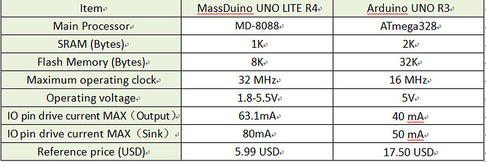
In this part, we use a Ardunio UNO R3 as a exmaple , and compare the MassDuino UNO LITE R4 with Arduino UNO R3, this will help users quickly understand the characteristics and advantages of our products.
[For details,please see the picture]

** If you want to know more about MassDrino, please visit the website of http://www.inhaos.com/or send email to supoprt@inhaos.com .**

Additional advertisements belong here.

Hi,
You really need to compare with the Pro Mini, where compatible copies are also $6 like THIS:

DISCLAIMER: Mentioned stuff from my own shop...

And there are $4 versions out there on Ebay.

Which ISA does the MD-8088 MCU use ?
-I can't find any details about it

I know this is an old thread but meanwhile INHAOS has released a new board.

As I am always in danger of running out of pins I look for Arduinos providing access to A6 and A7. I once tried to attach wires to the SMD chip myself. It worked but it's not safe.
So, eventually I found the Massduino which is prepared to fix extra pins for A6 and A7 on the board.
Delivery time was 23 days, and it was shipped in a solid cardboard box.
The INHAOS website tells you to install the Support package, and there is an instructable and a video how to proceed.
Actually, it looks this information refers to the ZIP-version of the IDE, telling you to move the support folders to the sketch folder. If you do this you won't find a Massduino board in the menu.
Nevertheless you can compile and upload sketches to the Massduino.
But the delay times don't match, and then you have to divide the baudrate of the serial monitor by four to read any text sent by the Massduino.
Once you move the provided files to the correct folder you will be able to select the Massduino board, and times and baudrates coincide.
The good news first: all the pins come in two flavors: male and female, and it comes with colorful headers.
When it comes to documentation all the infos on the Massduino controller MD328 are rather poor compared to the 660 pages provided by the Atmel-8271.pdf and the schematics by arduino.cc.
In the demo folder you will find four demos:
ADC_i2V26
it shows how to select an internal voltage reference of 2.26 volts
If you select this you can only measure voltages up to 2.56 volts. Voltages above don't destroy the Massduino but are also shown as 2.56.
And in the demo there is a reference to a pin called VCCM which cannot be accessed using any of the pins on the board.
So, what is the use of this demo?
Then there is the PEtest demo. It shows the usage of E0, E1, E2, E3, E4, and E5.
But it would not tell you which of the pins these might be.
And there are the demos DAC0_ramp and DAC1_ramp.
Nice to see the first one to produce an analog sawtooth on pin-4.
In the second one the comment tells you DAC1 is equal to PE5, and you can have the sawtooth there. But where is PE5?
So much for the demos.
The pdf-files included would tell you that you can benefit from enhanced ADC resolution by using readAnalog_12bits() and readAnalog16bits(). They both work but with increased noise.
Readanalog() will give you a noise level of just one unit whereas readAnalog_16bits() gives you more than 10 units of noise. So the gain is not as much as you would expect.
When it comes to FLASH memory, you are told the boot loader consumes 1024 bytes compared to the 512 bytes of OPTIBOOT.
When you check for EEPROM the doc would tell you: EEPROM 1 KB Share with Flash Memory (DOC-UNO-LC-V03- 20160415.pdf).
And, at the end of the day, you will find data written to EEPROM can be read also using pgm_read_byte(0x7800 + ofs).
But contrary to this doc, you have only 512 bytes of EEPROM, as the effective address is limited to 0x01FF in the library files:
EEARL = address & 0xff;
EEARH = (address >> 8 ) & 0x1;
So, the memory map actually is:
$0000 - $77FF FLASH ROM
$7800 - $79FF EEPROM
$7A00 - $7BFF unused ?
$7C00 - $7FFF BOOTLOADER
The question is: can the usage of this board be recommended? I am still in doubt.

It's me again; I realized a malfunction, so I got me another two samples of Massduinos: same results!
After two days of intensive testing these are my results:
In case you do something like this

#include <EEPROM.h>

byte LED_PIN = 11; 

boolean b;

void setup() {
  Serial.begin(9600);
  pinMode(LED_PIN, OUTPUT);
}

void loop() {
  Serial.println(EEPROM.read(123));
  digitalWrite(LED_PIN, b = !b);
}

after a short while the MD-328 controller will stop working; no more output to the Serial monitor and no more flashing LED.
PWM outputs will continue working, but ISRs won't be executed any more.
It is understood that frequent WRITING to the EEPROM will destroy it, but I am only READING. (o.k. this reading does not make any sense but it is not up to the controller to decide about this. Same result if I read different EEPROM addresses.)
Maybe the reason for the malfunction is the EEPROM is part of the FLASH memory.
Anyway, for projects where usage of EEPROM is essential the Massduino cannot be recommended.

Thats a shame..

and really, IMHO at least.. is up to @cywinhous to provide that information.

(I mean he spammed the boards with tons of other info... but not this?)

2 thumbs down from me.

I am still testing the Massduino UNO LC.
There are a lot of differences to the ATmega328.
After power-up all pins are supposed to show something near zero volts - not with the Massduino, many pins show 5 volts.
When it comes to Arduino commands, I often use PINB=0x20 to toggle the LED. Well, it compiles but nothing happens.
Actually, you can use digitalToggle(13); to do this. That's quite nice.

Then I tried to use the Digital-to-Analog-Converter which is contained in the Massduino (without using PWM and lowpass).
It is advertized to have DAC0 and DAC1, and demo sketches are delivered for both of them.
DAC0 works with Arduino-Pin-4, but you will look for the DAC1-pin to no avail.
When you check the doc file
http://www.inhaos.com/uploadfile/otherpic/UM-MASSDUINO-V3.0-EN.pdf
on the last page you find PE5 (=DAC1) is pin-6 of the controller, but no pin.
If you take a very, very close look at the board:

eventually you will find an eyelet, and the continuity tester confirms this pad is connected to PE5, DAC1.
To solder a wire to this pad is another story to be told.
At the end of the day, I connected one of the DACs with the analog input A0 to perform a self test.
Of course, the DAC accepts only values from 0 to 255, while the input gives values between 0 and 1023, so the latter ones where divided by 4.
In the Serial plotter, you would expect two identical linear lines.
Have a look at my results.
I still have to check if the input or the output has the non-linearity.

dac-adc.png

will you share others result if more about your experience with massaduino. most even high performance mcu need calibration tables a for the adc still nothing compared to the esp8266 or esp32 noisy adc.

transmissions4less:
will you share others result if more about your experience with massaduino. most even high performance mcu need calibration tables a for the adc still nothing compared to the esp8266 or esp32 noisy adc.

It's a detail, but the internal Vcc report function getBandgap() of the nano is not working on the Massduino.

IMHO readAnalog_12bits() and readAnalog_16bits() are only software extrapolations. Not worth to try.
The analogReference(INTERNAL2V56) delivers 1023 @ 2,5v, which ist OK.

Another peculiarity is the analog inputs. At least the one I have got, has an analog input pullup of 160 -180 Kohm. And I have not been able to make it behave floating like the at328.

Connecting a 100K NTC as in Ramps 1.4, an arduino uno shows the room temperature, around 21 degree C.
The md-328 shows 0 or minus degrees using the same circuit.

A small test program shows the difference between the two mcu's.

Something to consider when using analog input.

#define TIMEINTERVAL 1000     //Draw something every second
#define INPUT_PIN  A0
#define THERMISTOR_PIN  A0

#define LEDPIN  13

//Comment out to show voltage
//#define READ_TEMPERATURE

long drawingTime;

/***
* steinhart and thermistors
* https://arduinodiy.wordpress.com/2015/11/10/measuring-temperature-with-ntc-the-steinhart-hart-formula/
*                       _
*      vcc --v^v^---+---v\v^-- gnd
*            4.7K   |   100K NTC (NOMINAL_RESISTANCE)
*  (SERIESRESISTOR) |   
*                   +---||---- gnd
*                   |   10 microFarad
*                   v
*                  vo (A0/THERMISTOR_PIN)
*/


#ifdef READ_TEMPERATURE

float read_temp() {
 
 #define SAMPLES 4
 int rawvalue = 0;
 for(char i = 0; i < SAMPLES;i++) {
   rawvalue += analogRead(THERMISTOR_PIN);
   delay(1);
 }
 rawvalue /=SAMPLES;
 
 Serial.print("Analog read: ");
 Serial.println(rawvalue);   
 
 #define SERIESRESISTOR 4700.0
 #define NOMINAL_RESISTANCE 100000.0
 #define NOMINAL_TEMPERATURE 25.0
 #define BCOEFFICIENT 3950.0
 
 //Something wrong, short or no connection
 if(rawvalue == 0 || rawvalue == 1023)
   return 0.0;
 
 float steinhart = SERIESRESISTOR / ((1023.0 / (float)rawvalue) - 1.0) / NOMINAL_RESISTANCE; // (R/Ro)
 steinhart = log(steinhart); // ln(R/Ro)
 steinhart /= BCOEFFICIENT; // 1/B * ln(R/Ro)
 steinhart += 1.0 / (NOMINAL_TEMPERATURE + 273.15); // + (1/To)
 steinhart = 1.0 / steinhart; // Invert
 steinhart -= 273.15; // convert to C

 return steinhart;
 
}

#else

float readVoltage() {
 int rawvalue = analogRead(INPUT_PIN);
 Serial.print("Analog read: ");
 Serial.println(rawvalue);   
 return ((5.0* (float) rawvalue)/1023.0);
}
#endif

void setup() {

 Serial.begin(115200);
 while(!Serial);
 
 pinMode(LEDPIN, OUTPUT);

 drawingTime = millis() + TIMEINTERVAL;

}

void loop() {

 if(millis() > drawingTime ) {
   drawingTime += TIMEINTERVAL;
#ifdef READ_TEMPERATURE
   int temp = (int)read_temp();
   Serial.print("Degrees C: ");
   Serial.println(temp);
#else    
  
   Serial.print("V: ");
   Serial.println(readVoltage());   
#endif
   digitalWrite(LEDPIN, !digitalRead(LEDPIN)); 
 }

}