I have read that I can use my analog buttons as digital ones but doesn't seem to be working.
/*Press S6 to turn LED on and S7 to turn it off
and uses alalog as digital pin where S4 is on and S5 is off */

int LED = 13; //LED uses pin 13
int key_S6 = 2;
int key_S7 = 3;
int key_S4 = A7;  //key_S1-S5 uses analog input A7

void setup(void)
{
  pinMode(LED, OUTPUT);
  pinMode(key_S6, INPUT);
  pinMode(key_S7, INPUT);
  pinMode(key_S4, INPUT);
}
void loop(void)
{
  if(digitalRead(key_S6) == 0)
  {
    digitalWrite(LED, HIGH);
  }
  if(digitalRead(key_S7) == 0)
  {
    digitalWrite(LED, LOW);
  }
  if(analogRead(key_S4) == 0)
  {
    analogWrite(LED, 255);
  }
}
The digital buttons S7 and S8 and working to turn on and off the LED but S4 should also turn the LED on because I set the PWM to 255 which is all the way on. right?
Basically, it has buttons that read digital input and others for analog. This is my first arduino so that is the about extent of my understanding of it.
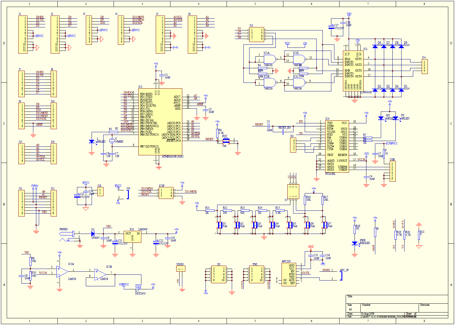
This schematic helps significantly: http://www.dfrobot.com/wiki/images/a/a0/RoMeo_Schematic.png
The manual for this thing is horrible. I think it is cute how they mention that S1-S5 are on an analog input, but don't bother to show how to use it or mention which Pin.
This Arduino varient takes advantage of the 2 (little know) additional Analog inputs provided by the ATmega, which is why A7 looks odd in the example code.
As noted, you can't PWM Pin 13. However a little known bug (feature?) of AnalogWrite is that if you AnalogWrite values greater than 127 to a non-PWM pin, it will write a HIGH. Regardless, you should be using digitalWrite(13, HIGH) for Pin 13.
Based on the schematic, S1 will return a value of 0 while S2 will return a value of 700mV. This means analog values between 0 and ~140 are probably S1. So you might change your "if-statement" to be:
if (analogRead(key_S4) <= 100) {
    digitalWrite(LED, HIGH);
 }
Thanks for you help. I got S1 to work with using >= 100 but not the other analog buttons.
Based on the schematic, S1 will return a value of 0 while S2 will return a value of 700mV. This means analog values between 0 and ~140 are probably S1.
How did you determine from the schematic that S1 will return a value of 0 and S7 700mV. Then how did you determine from there that the analog values would read b/t 0 and 140?
Well you could calculate it but it is simpler just to read the value and print it out so you can see the voltage given by not just the individual buttons but all the combination of buttons.
The resistors attached to each button creates a voltage divider.
As mike suggests, the easiest thing to do is write a sketch that prints out of the value of the analogRead. Then go through and press each button. Just remember that you are reading an analog input. So if one of the buttons returns 143 today it might return 141 or 144 tomorrow.