I have a problem to interface a RTD converter with an Arduino Uno.
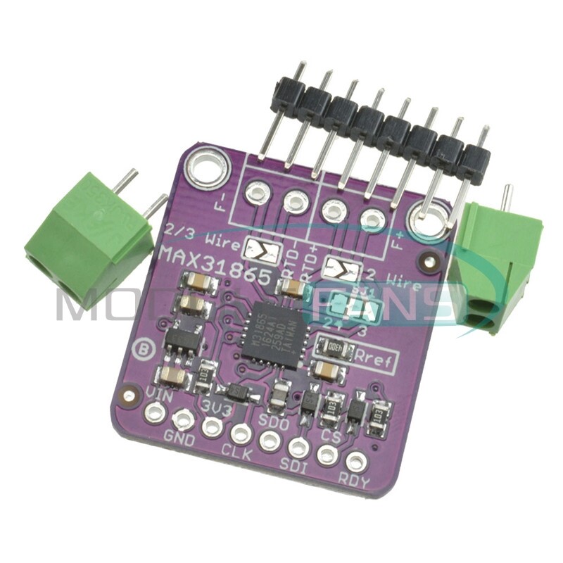
I bought the violet board, see attachment.
I connected the converter with the Arduino, I used the library for the Adafruit PT100 RTD Temperature Sensor Amplifier - MAX31865 that looks very similar to this board. The circuit works but the problem is that it read not correct values. I used as simulator a FLUKE 726 precision calibrator, so pretty sure about the temperatures simulated. When simulated 0 degrees the MAX31865 ADC converter MSB register is already 13566, increasing the temperatures up to 100 degrees the ADC is already 32251 and simulating 109 degrees the register overflow because it reach 32768 value and I receive back from the board the RTD HIGH TRESHOLD alarm. So all seems to work, but the temperatures read by the ADC converter and stored in the MSB register are extremely high and not allow to read temperatures above 108 degrees Can someone help to solve the issue? Can you recommend a library and an example?
The board I'm using is showed in the picture attached that looks identical to the Adafruit board mentioned at this link Overview | Adafruit MAX31865 RTD PT100 or PT1000 Amplifier | Adafruit Learning System
I'm using an RTD 4 wires, so according with the specification I didn't modify the on board jumpers.
On the link you find the code I'm using, connection are with Arduino Uno pin 10,11,12,13 10 that meas 13 SCK 12 SDO 11 SDI 11 CS. The board respond to serial communication well so no doubt regarding connections, the problem I'm facing is in the value that the MAX31865 chip is giving back. Library I'm using is the recommended download Adafruit_MAX31865 from our github repository and the sketch is the example of the library.
The example uses a software SPI. Change the constructor call to the commented out version with just one parameter and comment the 4-parameter call out to use the hardware SPI interface.
Measure the reference resistor on your board (Rref) with a multimeter. What value do you get? How do you power the board? Is the wiring exactly a proposed on the linked page (no connection to 3V3)?
Thank you so much for your reply.
The reference resistor is approx 430 ohm.
I powerd up the board with 5 volt, no connection on 3.3 volt, there is a 5 to 3.3 V integrated on the board.
5 V supply is the same of Arduino.
Can you explain me better what I have to change on software side?
Thanks again, much appeciated
Something tells me that there is a hardware problem with these boards. I bought six of them an none could give me a correct RTD value (always zero, using the Adafruit library).
Something tells me that there is a hardware problem with these boards. I bought six of them an none could give me a correct RTD value (always zero, using the Adafruit library).
Do you have the PT100 or PT1000 version of the Adafruit board? Does it correspond with your RTD?