4" common anode 7-segments: driver reference to buy in 2014

Hello guys :slight_smile:

I would like to drive a 4" large 7-segments LED with my arduino nano.

This 7-segments is common anode
and 12V driven.
I have understood I have to use a Constant-Current LED Sink Driver
(sink and not source because of common anode).

I wish you could tell me what reference of driver I could buy in 2014?
as I have googled many threads but often the chip references are outdated... :~
(Allegro 6278EAT from this post on deleteaso.com)

Could you please tell me what I can buy?

Thanks
yours
Mat

PS : I know there is an alternative but I would like to not use 7 NPN transistors and 14 resistors to simplify the wiring.


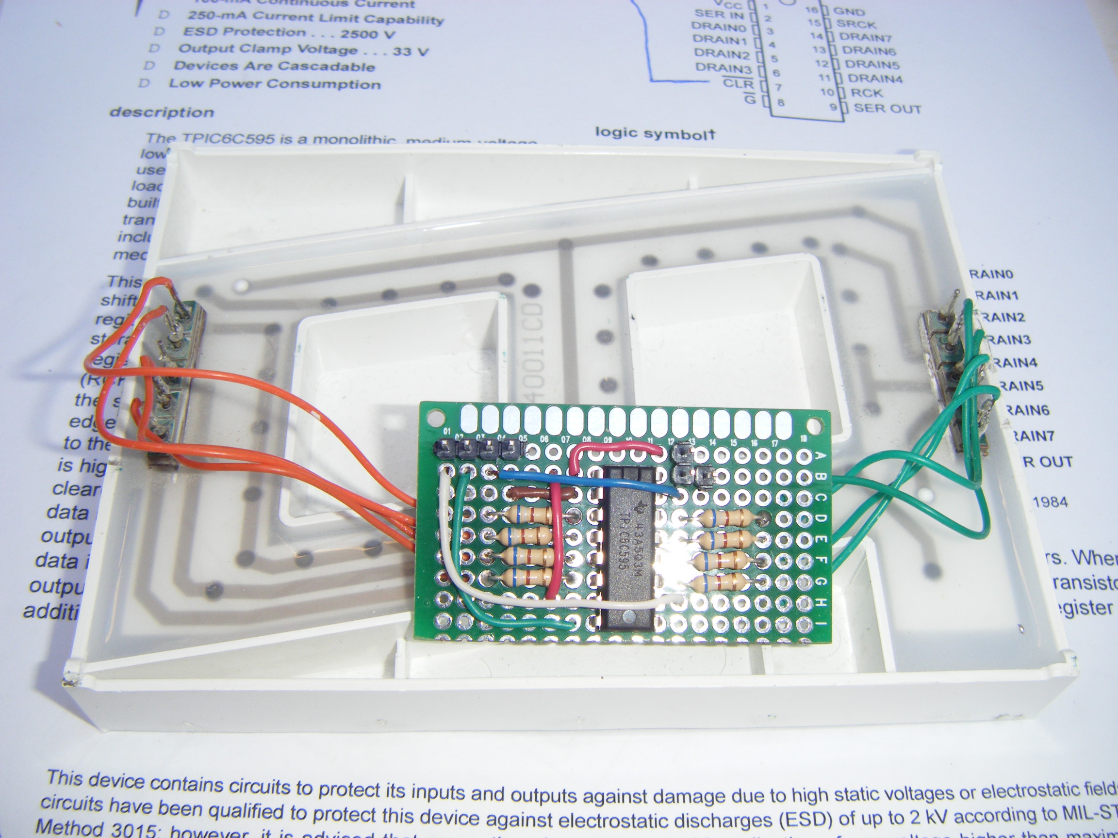
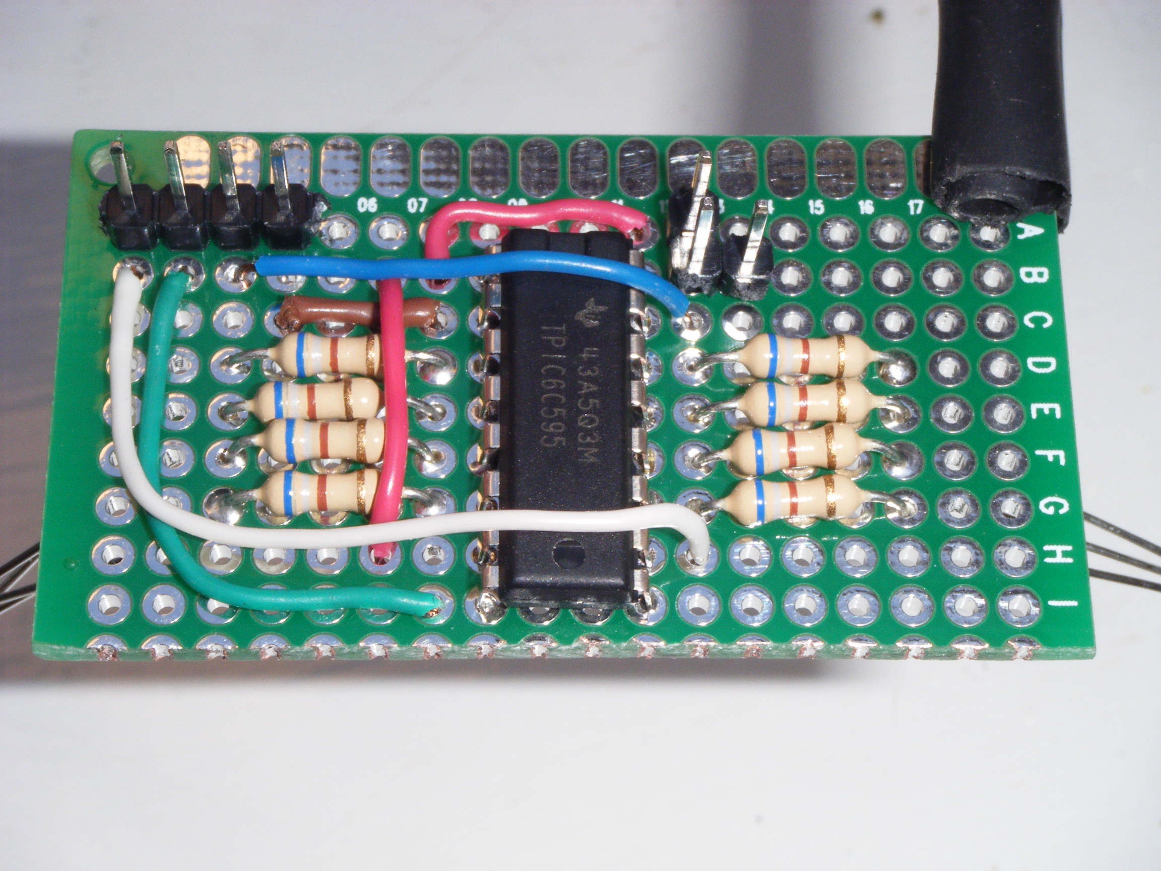
edit : here is what I have done
thanks to PaulRB, CrossRoads, Grumpy_Mike, Paul__B !

-> job done with TPIC6C595

see in attachement PCB and wiring diagram

  • arduino SPI library

Here is the result in video!

Thanks guys for the help so far!

/*
 Shift Register Example for 74HC595 shift register by Tom Igoe
 Digital Pot Control  by Tom Igoe
 Thanks to Heather Dewey-Hagborg for the original tutorial, 2005
 Thanks to CrossRoads!
 by RacingMat 09-2014
 */
// include the SPI library:
#include <SPI.h>

byte fontArray[] = {
  // dp-a-b-c-d-e-f-g
  0b11101110, // 0
  0b00101000, // 1
  0b11001101, // 2
  0b01101101, // 3
  0b00101011, // 4
  0b01100111, // 5
  0b11100111, // 6 
  0b00101100, // 7
  0b11101111, // 8
  0b01101111, // 9
  0b00010000, // DP
};

//Pin connected to Data in SER IN pin 2 of 6c595
const int dataPin = 11;
//Pin connected to latch pin (SRCK)pin 15 of 6c595
const int latchPin = 13;
//Pin connected to clock pin (RCK) pin 10 of 6c595 as the slave select
const int slaveSelectPin = 10; 

void setup() {
  // set the Pins as output:
  pinMode(dataPin, OUTPUT);  
  pinMode(latchPin, OUTPUT);
  pinMode (slaveSelectPin, OUTPUT);
  Serial.begin(9600);
  // initialize SPI:
  SPI.begin();
  // take the SS pin low to select the chip:
  digitalWrite(slaveSelectPin,LOW);

}

void loop() {
 for (int i=0; i <= 10; i++){
      delay(500);
    digitalWrite (slaveSelectPin, LOW); // << RCLK line goes low
    SPI.transfer (fontArray[i]);  //  << SRCLK goes  high-low 8 times to output 8 bits of data
    digitalWrite (slaveSelectPin, HIGH); // data outputs change on this rising edge << RCLK line goes high to move data into output register
  }
}

http://www.led-display.cc/Single-Digit-LED-Display/67/LD40011CD-4-Inch-Single-Digit-7-Segment-LED-Display.htm


edit :

Some news:
this video to demonstrate how Simtools can extract data from racing games in real time

it's really synchronized between GT Legends and the LDC display :slight_smile:

Physically how will the digit to display be transmitted to the Arduino?
It is via a USB com port

There are two free softwares which can drive actuators for dynamic simulators and dashboard incidentally
-Simtools software
-xSim software with an example of more complex digital dashboard

downloadfile.png

Hi Mat and welcome.

I would consider uln2803, tpic6c595 and saa1064. The '2803 and '595 do not contain constant current drivers but you can use series resistors instead. The advantage of the '595 is that it would use only 3 arduino outputs and the chips can be daisy-chained to drive more digits. The advantage of the '1064 is that it could drive 2 such displays, or even 4 with the addition of a couple of transistors. Also it would use only 2 arduino pins, since it connects via the i2c bus. It contains constant current drivers and has 7 brightness levels that can be selected in software.

Paul

Thanks PaulRB! :slight_smile:

I would like to build several "gear indicators" for my simracing cockpit 8)

My use is really basic, no daisy chain, only one digit:
so saa1064 is over-mighty (and expensive)

uln2803 = 1,12€ / 10 pcs http://www.ti.com/lit/ds/symlink/uln2803a.pdf
tpic6c595 = 1,90€ / 1 pc + 3€ http://www.ti.com/lit/ds/slis061c/slis061c.pdf
and saa1064 = 2,50€ / 1 pc + 2,5€ http://www.fortito.mx/wp-content/uploads/technical/SAA1064.pdf

I'll now check what would be different between uln2803 and tpic6c595...

Another suggestion is tlc5916/7.

Or bc337 (x7)!

Why do you believe you need constant current drivers?

What is the forward voltage of the segments in your displays, and the maximum current?

How will your circuit know what digit to display?

Thanks, I'll check the new references you gave me!

Why do you believe you need constant current drivers?
I thought that with such a driver I won't need to add resistors and simplify my wiring, no?

What is the forward voltage of the segments in your displays, and the maximum current?
I recycled these 3" 7-segments so I haven't the specs.
I did some tests to determine that they are common anode.
and below 12V, they don't lit...
About max current, I'm not sur how to know it without burning them :smiley:

How will your circuit know what digit to display?
They are some dedicated free softwares that extract telemetry data from games 8)
I may link them later today if you're interested in!

You are correct, without constant current drivers, you will need series resistors. If using transistors you will need even more resistors on the bases. But transistors and resistors are very cheap!

How much below 12V will the segments still light? All driver chips will drop some of the supply voltage, and if that is 12V also, you may have a problem.

Normally there is a part number printed on the side of such displays. Can you see one? Have you googled the part number?

Physically how will the digit to display be transmitted to the Arduino?

TPIC56x595 are good. 6B595 is 150mA, look also at 6A595, 6C595, 6D595, one of them is 100mA/segment and 20V source, lower cost but all the capability needed.

Open drain outputs, will have low voltage drop across them compared to ULN2803, which does not have shift register built in like the '595s are.

@CrossRoads: Thanks for your help!
Yes, a built-in shift register is a nice feature!
I'll read the specs
tpic6a595
TPIC6B595

@PaulRB:

Physically how will the digit to display be transmitted to the Arduino?
It is via a USB com port

There are two free softwares which can drive actuators for dynamic simulators and dashboard incidentally
-Simtools software
-xSim software with an example of more complex digital dashboard

How much below 12V will the segments still light?
5V is not enough, 12V was good: I'll redo some more tests

Normally there is a part number printed on the side of such displays.
Yes I have googled the references without luck (I'll write them here once back home)

Arguably, ULN2803s are undesirable for most applications. The use of Darlington pairs means that they have a poor saturation voltage - of the order of 1V which is of course, a significant voltage loss in a 5V circuit and a dissipation of 1 Watt per Amp switched. They also draw base current even if no load is connected.

Where you wish to use a shift register, a TPIC6x595 is a vastly better performer, with an essentially zero quiescent current. An array in a chip with only the logic level power FETs would be ideal for other applications.

Paul__B:
An array in a chip with only the logic level power FETs would be ideal for other applications.

That would be a useful part to keep in our part boxes. Do we know of one?

Hi,

the references are CILE40011CD molded into the plastic
and maybe a part number printed J40011AR-2

I had no luck...

Are you sure the display is 3"? The data sheets for displays with similar codes are all 4". What colour are the segments when lit?

This is the best match I can find for the data sheet:

http://leds.com.ua/assets/products/datasheets/92.pdf

The forward voltage depends on the colour but most are quoted as 2.1V. There are 5 leds shown for each segment (except the dp - be careful with that!) which would make the total 10.5V for the segments (but only 2.1V for the dp).

Hey! you're great! 8)
They are 101mm high which is ... 4" digit height : sorry I'm not acustomed to imperial units :blush:
And the color is red.

And I hope I didn't mistake: it is common anode because I had to plug the common pin to +12V and others pins to ground to lit the segment.

Please can you tell me what hints the specs are giving to choose the driver?

(I have understood that the dp should not be fed with 12V because there is only 1 LED inside: thanks).

We don't know for certain that those are the specs. The product code is not an exact match. You should be cautious. But if they are correct, all the suggestions so far should be ok, even the uln2803. If the max current is 20mA then a series resistor of (12-10.5)/.02=75R should be ok, but start with a 100R first. If the segment does not light, try a lower value. Once the segment lights, measure the voltage accross the resistor. From that you can calculate the forward voltage of the segment and the current through it. Let us know what you find.

Most large digits like that are 3 or 4 or 5 LEDs in series, such as this

Flip all the LEDs over and it is common anode.
TPIC6c595 is perfect for driving, use 1/digit for a non-multiplexed display.
Create a font array and send out a byte per digit:

byte fontArray[] = {
0b00111111, // 0
0b00000110, //  1
:
:
0b01101111, // 9
};

0bDP-g-f-e-d-c-b-a, a bit =1 is an on segment
a
f b
g
e c
d DP

digitalWrite (RCLK, LOW);
SPI.transfer (fontArray[numberToDisplay[0]]); // double lookup!
SPI.transfer (fontArray[numberToDisplay[1]]);   // data goes on MOSI with SCK to SRCLK pin
SPI.transfer (fontArray[numberToDisplay[2]]); 
SPI.transfer (fontArray[numberToDisplay[3]]);  // OE/ tied Low or PWM for brightness, SRCLR tied to +5
digitalWrite (RCLK, LOW); // data outputs change on this rising edge

PaulRB:

Paul__B:
An array in a chip with only the logic level power FETs would be ideal for other applications.

That would be a useful part to keep in our part boxes. Do we know of one?

This is the only thing I could find:

http://www.digchip.com/datasheets/download_datasheet.php?id=2605607&part-number=AN01&show=inline

Continuous current rating is very low. TPIC6x595 much better in place of this, 8 outputs with 3 control pins vs needing 8 on this device.
Check Mouser for current availability of Supertex parts.
http://www.mouser.com/Search/Refine.aspx?Keyword=supertex

CrossRoads:
Continuous current rating is very low. TPIC6x595 much better in place of this, 8 outputs with 3 control pins vs needing 8 on this device.
Check Mouser for current availability of Supertex parts.
Search results for: supertex – Mouser Europe

Agreed, it looks inferior to tpic6c595. But Paul__B posed the question is there a fet equivalent to uln2803, which has a rather high voltage drop (~1V) due to its use of darlingtons.

Mat,

Looks like uln2803 will be the most cost effective part part. However, to be sure it will be suitable, you need to measure the forward voltage of those segments, to confirm it is around 10.5V. Connect a 1K resistor to one segment and your 12V to the anode. This should not light at all. If it does light anthing more than a faint glow, we have the wrong data sheet!

Assuming 1K does not work then try 100R. Hopefully the segment will light, although it may be dim. If it does not light, try a lower value like 68R. When the segment lights, measure the voltage accross the segment and accross the power supply (which is regulated or switch-mode, yes?).

Once you have measured the forward voltage, you can then calculate the correct resistor to give a nice bright display.

PS. Uln2003 is similar to uln2803 but with only 7 outputs, so that will also be suitable, if you do not want to use the dp.

However, if in the future you wish to expand the project and connect more displays or other things to the arduino then the tpic6c595 will leave more Arduino pins free.