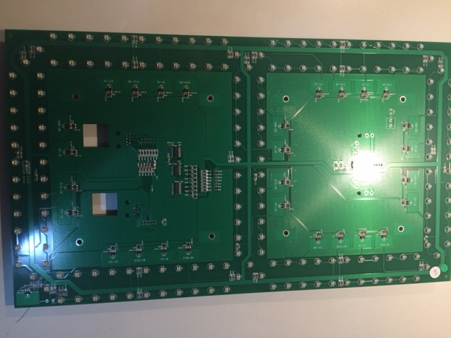
Yes, an arduino is a good way to do this.
I would start by writing some code that will drive the 7-segment display. I would build an object that looks like this:
SevenSeg {

  const byte dataPin;
  const byte clockPin;

  byte data[4]; // we have four 7-segment displays


  SevenSeg(byte attachData, byte attachClock) :
    dataPin(attachData),
    clockPin(attachClock)
  {
  }

  void setup() {
    pinMode(dataPin, OUTPUT);
    pinMode(clockPin, OUTPUT);
  }

  void update() {
     // code goes here to send the correct chain of bits
     // to the 7-segment latches
     // hint: seer the 'shiftOut' function ion the standard library
  }
};


SevenSeg display(2, 3); // data pin 2, clock pin 3


void setup() {
  display.setup();
}

void loop() {
  static uint32_t mostrecentUpdateMs = 0;


  if(millis() != mostrecentUpdate) {
    mostrecentUpdate = millis();

    display.data[0] = mostrecentUpdate;
    display.data[1] = mostrecentUpdate>>8;
    display.data[2] = mostrecentUpdate>>16;
    display.data[3] = mostrecentUpdate>>24;

    display.update()
  }
}
Your goal is to fill out the update method to the point where you can see the segments at least lighting up.
From there, instead of just showing garbage on the segments, we'll alter it to make all the segments light up in sequence
  static uint32_t mostrecentUpdateMs = 0;
  static int currentBit = 0;


  if(millis() - mostrecentUpdate >= 500) {
    mostrecentUpdate = millis();

    currentBit = (currentBit+1) % 33;
    uint32_t bits = (0xFFFFFFFF) >> (32-currentBit);


    display.data[0] = bits;
    display.data[1] = bits>>8;
    display.data[2] = bits>>16;
    display.data[3] = bits>>24;

    display.update()
  }
}
This should make the segments light up in sequence - a to g. If they don't, then you'll need to tweak 'update' so that they do.
Once that's done, you can turn your attention to parsing the incoming data stream. The thing is, of course, that bytes come in one at a time. I tend, again, to make a parser object.
class ProtocolParser {
  byte data[4];

  void addByte(byte b) {} // add a byte to the frame
  boolean ready() {} // signals that a frame is complete
} parser;


void loop() {
  int ch = Serial.read();
  if(ch != -1) {
    parser.addByte((byte)ch);
    if(parser.ready()) {
      memcpy(display.data, parser.data, 4);
      display.update();
    }
  }
}
The job of the addByte method is to work out what to do when it gets a byte. This depend on how many it already has, of course.
It needs to watch for the stop bytes, pull out the data bytes and put them into the data array, and it should verify the checksum. If the checksum is ok, then it will set some internal 'ready' flag that stays set until it is given another byte. To do this, it needs some private internal variables that keep track of where in the frame it currently is.
parsing can be a complicated job, although if your connection is pretty reliable you could just go with counting.
Anyway. That's how I'd do it. The benefit of using a class for the parser is that it becomes much easier to test - feed in some bytes from an array that you build by hand to test it. Once it seems to work, turn it loose on the real data stream. If the parser is integrated into the body of your code, you have to do a fair bit of violence to things to do that. When it's encapsulated in a class, it's quite a bit easier.
And you can re-use your 'seven segment' class in other projects.
