Hello 
I have RGB LED matrix strip.
16 leds , connected in matrix
IC is MAX 7219 , I have run it on this sketch. So can you help me to change the program. It was working but not very nice , not in order , mixed up and so on. Some advice for changes in program to do it better. Thanks
#include "LedControl.h" //  need the library
LedControl lc=LedControl(12,11,10,1); //

// pin 12 is connected to the MAX7219 pin 1
// pin 11 is connected to the CLK pin 13
// pin 10 is connected to LOAD pin 12
// 1 as we are only using 1 MAX7219

void setup()
{
  // the zero refers to the MAX7219 number, it is zero for 1 chip
  lc.shutdown(0,false);// turn off power saving, enables display
  lc.setIntensity(0,8);// sets brightness (0~15 possible values)
  lc.clearDisplay(0);// clear screen
}
void loop()
{
  for (int row=0; row<8; row++)
  {
    for (int col=0; col<8; col++)
    {
      lc.setLed(0,col,row,true); // turns on LED at col, row
      delay(25);
    }
  }

  for (int row=0; row<8; row++)
  {
    for (int col=0; col<8; col++)
    {
      lc.setLed(0,col,row,false); // turns off LED at col, row
      delay(25);
    }
  }
}
Hi,
Could you please edit your original post and put the code inside [ code][ /code] tags.
It's a little bit difficult to help you modify your code without an actual schematic. What I can say is that your code assumes 8 rows by 8 columns, which is 64 LEDS. You only have 16 LEDS. This is the source of your ordering problem, but without a diagram showing how you've wired up the LEDS it's a bit hard to tell which lines to change.
i am sorry , new around here so still learning.
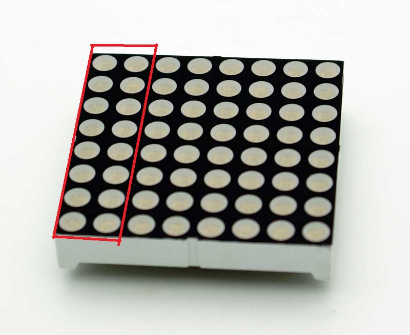
LEDs are connected like a regular 8x8 matrix, but only the firs two rows.
see image.
So the first 8 LEDs. example , all RED pins are on the same wire go to pin 6 (DIG2) on MAX7219
all GREEN are on the same wire go to pin 11 (DIG1) on MAX7219
and so BLUE too on the same wire go to pin 2(DIG0) on MAX7219
so i have divide strip on two parts , first 8 LEDs, and second 8 LEDs.
grounds are connected in this way , first part leds and second part led goes like this : 1st-9th , 2nd-10th , 3rd-11th , and so on to 8th-16th.
grounds are go to pins : 23 (SEG D), 22 (SEG DP) , 21 (SEG E) , 20 (SEG C) , 17(SEG G), 16 (SEG B), 15 (SEG F), 14 (SEG A) on MAX7219.
Sorry you might know what you are doing but I find your explination confusing. The photos suggest an common anode led is that right.?
Please supply a schematic, after all if you don't have a schematic you don't stand a chance of making it.
Well that's half of a schematic but what pins to all those unconnected wires go.
Your phrase:-
grounds are go to pins : 23 (SEG D), ..............
Puzzles me, are these pins actually connected to ground?
Yes thats right ,my mistake yesterday I was unable to know right pinout. LEDs are comonn anode.
you see that is two wires of RED , GREEN and BLUE. So RED wire are connected to PIN 6 and 13. GREEN wire go to PIN 11 and 3.
BLUE wire go to PIN 2 and 7.
And ANODES 1st-9th , 2nd-10th , 3rd-11th , and so on to 8th-16th.
(correction) ANODES go to pins : 23 (SEG D), 22 (SEG DP) , 21 (SEG E) , 20 (SEG C) , 17(SEG G), 16 (SEG B), 15 (SEG F), 14 (SEG A)
23pin = 5th-13th.
22pin = 1st-9th.
21pin = 6th - 14th.
20pin = 4th-12th.
17pin = 8th-16th.
16pin =3th-11th.
15pin = 7th-15th.
14pin = 2nd-10th.
Sorry, I'm finding it very difficult to understand your explanations. A proper schematic would make this a lot easier.
RED wire are connected to PIN 6 and 13
Unlikely. Pin 13 is CLK.
To fix the LED ordering you were talking about, try reversing your columns and rows in the code. The lc.setLed() function specifies row,col not col,row if the matrix is set up as per the examples. It's the best I can offer without a proper schematic.
void loop()
{
  for (int row=0; row<8; row++)
  {
    for (int col=0; col<8; col++)
    {
      lc.setLed(0,row,col,true); // turns on LED at row,col
      delay(25);
    }
  }

  for (int row=0; row<8; row++)
  {
    for (int col=0; col<8; col++)
    {
      lc.setLed(0,row,col,false); // turns off LED at row,col
      delay(25);
    }
  }
}
here is for this code. Short video how it works.
void loop()
{
  for (int row=0; row<8; row++)
  {
    for (int col=0; col<8; col++)
    {
      lc.setLed(0,col,row,true); // turns on LED at col, row
      delay(25);
    }
  }

  for (int row=8; row>0; row--)
  {
    for (int col=0; col<8; col++)
    {
      lc.setLed(0,col,row,false); // turns off LED at col, row
      delay(25);
    }
  }
}
SAM_2591.AVI (2.01 MB)
here is for this code.
No that is just a bit of the code.
You need to post all of it, and say what it does and say what you want it to do, to give us an even chance of helping you.
Grumpy_Mike:
here is for this code.
No that is just a bit of the code.
You need to post all of it, and say what it does and say what you want it to do, to give us an even chance of helping you.
In fairness to the O.P., he did actually post the complete sketch at the top of the thread, and sort-of described what he wanted. But, he hasn't given an accurate schematic or even description of how it is wired up, which makes it impossible to determine what the problem is.
I would imagine the anodes are connected to segment pins on the MAX7219, while the common cathodes are connected to digit pins on the MAX7219.
Then SPI could be used to control the MAX7219 - SCK (D13) to Clock, MOSI (D11) to Serial data, and SS (D10) to Load (CS/).
But, he appears to be using the LED Control library instead, which bit bangs the control lines out:
#include "LedControl.h" // need the library
LedControl lc=LedControl(12,11,10,1); //
// pin 12 is connected to the MAX7219 pin 1
// pin 11 is connected to the CLK pin 13
// pin 10 is connected to LOAD pin 12
It was working but not very nice , not in order , mixed up and so on.
I cannot tell what is expected to operate differently.
Some advice for changes in program to do it better.
Same here. Do what better? Seems pretty compact as it is.
CrossRoads:
Some advice for changes in program to do it better.
Same here. Do what better? Seems pretty compact as it is.
I think his English is getting in the way here. I think by better he just means make it work the way he wants it to (which I'm guessing means left to right, rather than the current order).
But, beyond the earlier suggestions, I don't know how to help without a proper schematic.
Thanks for your time and effort.
I need some time to find proper schematics.
Thanks alot anyway.
I need some time to find proper schematics.
No you need time to DRAW some proper schematics.
here you go.
now is connected like this ..
don't know why is that "red" connected on pin 13.
this is from my school , and i got it like that
it must go on some "DIG" pins on MAX7219.
thanks
LEDmatrix.sch (179 KB)
You need a 0.1uF cap, and a larger electrolytic cap, 1uF would be good, on the +5V line.
The one connection around the bottom up to pin 13, that's not correct. That will keep the clock input line from working correctly. Move that to pin 10.
Yeah, that pin 13 is definitely wrong. That's why you are getting the left and right leds both on at the same time. Change that and then let us know what your leds are doing.
Here's his diagram shrunk down a bit.
here I put that caps on 5V , more stable voltage for IC or? .
and video how LEDs now working
SAM_2622.AVI (2.45 MB)
Yes, the caps provide more stable voltage when the clock changes and the outputs change and there are little current surges going on.
Really important if you use SPI for data transfers instead of bit-banging the signals.