Hi, I purchased a 7-segment display but am having difficulty getting it working. I do not know if it is has a common cathode or anode. There was a no datasheet with it as it came in a bag or assorted displays. I also am not sure of the pins. The ten pins are down the side and not along the top as in nearly all the displays I've seen online.
The pins seem to be: (cc=common cathode, ca=common anode)
The following programme sets all pins on my Arduino Uno board from 2 to 9 to high. I can light any segment but only one at a time, by connecting the GND to A,B,C,D,E,F or G and having the cc/ca connected to any of the pins from 2 to 9. But how can I use the Arduino to light up different combinations of segments?
Hi ofey. First...good find... cheap parts... Ok for testing 7 Display, put the display into a breadboad, place a 470 ohm at any Pin location of the 7 Display, take a wire - positive to resistor side and use the negative to touch any pin until you have one light up.
Make sure you use a 5 V supply. And repeat the process until you check all the pins of the display.
to check you program, you can use LEDs with resitors, I you find the pinout of the display, use resistor of 470 for each segment and connect the CC/ CA to GND or +5.
I feel much better if you use a transistor to control the LED / segments.
To test and use Arduino, use the code. Just loop the leds.
for ( int led=1; led<=7; lled++)
{
   digitalWrite( led, HIGH);  // for CC , for CA use LOW
   Delay ( 1000);
}
'ello
I'd recommend using a guide like this Make: Projects.
The first thing I learned when hooking up the display was that the two cc/ca pins were hooked together and then connected to either ground (cc) or power (ca).
To turn each segment on, you'd have to to a digital write inverse of the cc/ca pins.
So a CC would need a digital 1 (5v) to turn on, while a CA would need a digital 0 (0v) to turn on.
I just saw your video. I am sorry the second video things is not working. I saw the first was working, and you did move the GND wire to some of the segments ( lighting up ) and the second video ( not light up ) . Conclusion : The 7 segment is a CA - Common Anode Type. to make things work, you connect to +5 V ( the CA pin ). But in the code, you use the line "digitalWrite ( 5, HIGH ); " That is why in the second video things was not working. But It will work with a CC type. So change the code to digitalWrite( 5, LOW); As long the CA is connect to +5. The rest is to connect 6 wire from Ardiuno - resistor 470 and to each segments and CA to +5. just like the second video. Just connect the rest of the segment. To light up, make sure in the program code is digitalWrite( pin, LOW ). So the connection should be ---- pin - resistor---led---+5 . Sorry that I repeat myself.
When I have a Display, I do look up the datasheet, and I do a live test with a +5, 470 ohm and some wires. Mark down the info ( pin , segments, CA or CC ) Sometime, the datasheet is hard to find.
@FC
You right about it. In CA mode, the Ardiuno output pin will be in "current sink" mode to display any LEDs and in CC mode, it is in "current source".
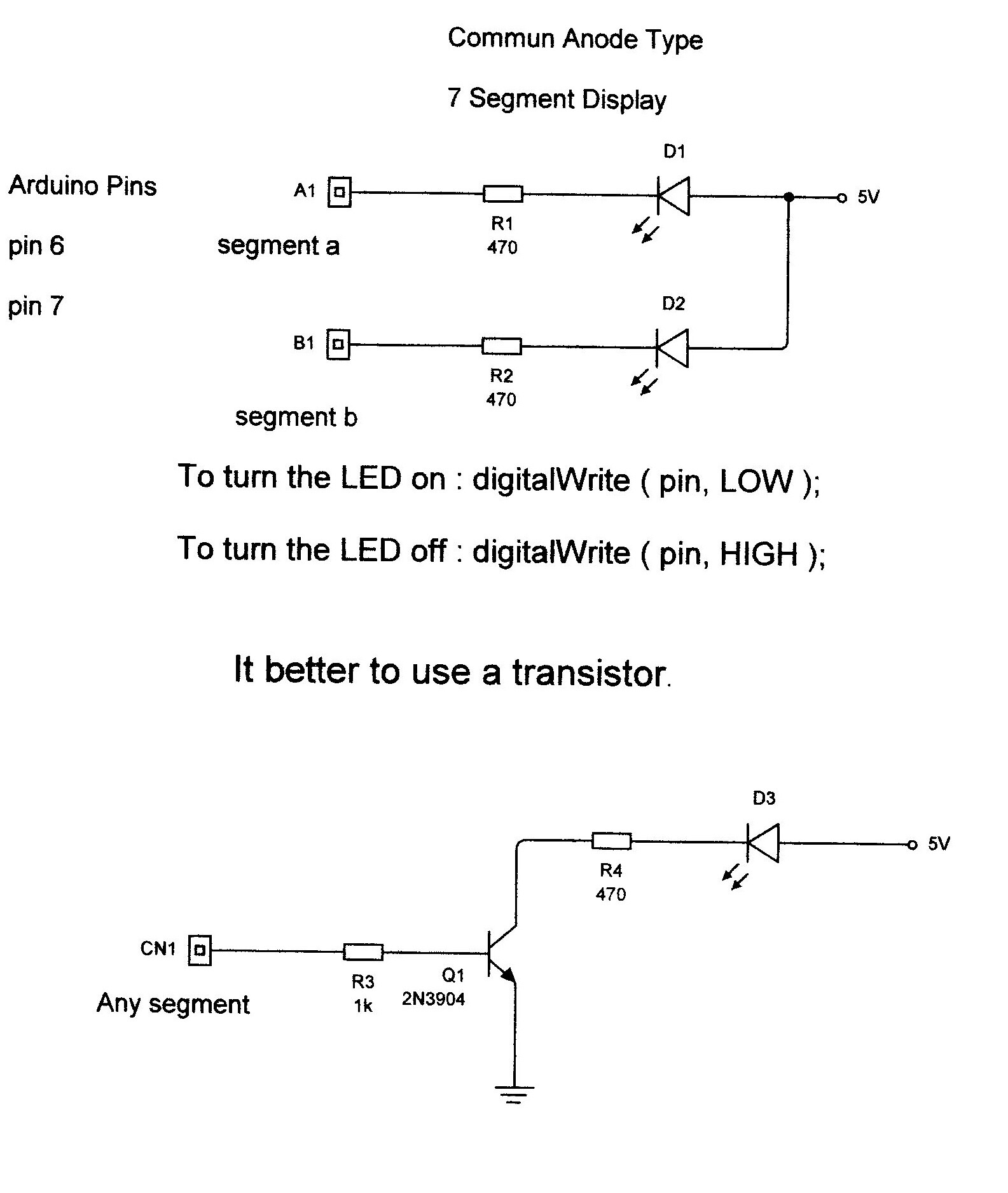
Here a schmatics to how to connect display or LED's.
To all: Here a link of a distributor in Toronto who carry Knight Lites products. The link going to a page where you can click on any leds and it will show the datasheet. I was having a hard time to find the site of Knight Lites Ltd. http://www.transcanadaelectronics.com/knight_lites_cat.phtml
I forgot...when you use the transistor circuit, you have to use digitalWrite( pin, HIGH); A high ( +5 ) will turn on the transistor and turn on the LED. The transistor circuit is the safest to use with you Arduino. And you can use a different voltage for the Leds, but the resistor have to be re-calculate.
Here the formula : Limit Resistor = ( Supply Voltage - Voltage of LED ) / Current of LED <-- Keep in the range of 5mA to 10mA
You've all been fantastic, I really appreciate the help. It is working now.
So first Techone as you said this is a common anode type display, therefore the common cathodes have to be connected to the 5v with a 470 ohm resistor on each. And also only the pins that are set to low will light the LEDs as you said.
Here's a video of it working in case it might be of help to anyone else. (After making this I did connect a 470 ohm resistor to each of the LEDs.)
(Sorry I took so long to get back, I was waiting for an email to say that there had been a reply but that wasn't set up correctly. )
"this is a common anode type display, therefore the common cathodes have to be connected to the 5v with a 470 ohm resistor on each. "
If common anode, then the anode goes to +5V, and the individual cathodes get a resister to ground (or a low output pin) to turn them on.
Having a single resister to the anodes which are connected internally (thus two 470s in parallel are same as single 235 ohm) means that for a single segment, the arduino pin will be sinking (5v-2V)/235 = 12.7mA. (put in your LED forward voltage for a real current #).
If 2 segments are on, the 12.7mA is shared, and it will drop as more segments turn on, so the brightness will appear to change.
That's why we use a resistor on each segment vs a common resister on the anode, so the current will be the same for all LEDs.
I'd draw up a simple schematic, but its too hot out ...
I did upload a schematic, just click the link, chose open and it will view using Explorer. ( That work for me ) if not work, just choose save in one of your directory.
It should be - a resistor for each segments and connect the CA to the +5 V and code digitalWrite ( pin , LOW ) to turn them on . or use a transistor. It is more safe. And could use digitalWrite ( pin, HIGH )
I know, it could be a bit confusing.
Why I choose 470 ---> ( 5 - 2 ) / 470 = 6.38 mA <-- I feel safer for the Arduino.
So I took out the resistors on the cathodes and connected that directly to the 5v and everything is brighter and also all LEDs are as bright and I noticed how they weren't before. There was a difference between digits 8 and 1.
But now they are a bit too bright. Is the only way to dim them to put larger resistors on each LED (anode)?
Using Techone's formula
Limit Resistor = ( Supply Voltage - Voltage of LED ) / Current of LED <-- Keep in the range of 5mA to 10mA
The voltage between the cathode and anode is 1.87 and suppose I just take the current of the LED to be 5mA,
626 = (5 - 1.87) / 0.005
So it looks like the resistors connected to each LED should be about 560 or 680 ohms. I think they are the usual standards. Is that correct?
Here a photo of LEDs connected like a Commun Anode mode. I use transistors to turn the leds on. The transistors are MPS2222A. They are NPN. A CA device are often use in "open collector". Meaning a LOW signal - "sink mode" will turn the device on. The transistor is being turn-on by a HIGH signal, the voltage at the collector is 0 V. In the picture, you connect the Arduino pin at the 1 K resistor.
I know it is not a 7 segment display, It is just an example.
Yes. It a NPN. From left to right. Emitor - Base - Colector --> E B C
Would the arduino board pins be connected to the far side of the resistor connected to the base (middle) of the transistor?
Yes. The resistor connected to the base is 1 K - Brown - Black - Red - Gold
Is the bottom rail gnd and the top rail 5v?
Yes it is. Bottom Rail is GND. ( sorry for the red wires ) Yes it is. The top is +5 V ( It could be other voltage - option )
This is the standard to connect any "load" ie LED control by a logic gate or in the case an Arduino. For a CA 7 segment, you need 7 transistors, 14 resistors ( 7 for each LEDs and 7 for each transistors ). In your case, it is an optional way to light your 7 segment display.
@CrossRoads
I know it is "overkill". I just like to keep a "standard" way to do my designs / circuits.
Using ExpressSCH to show schematics. I will try it.