Link Arduino to Raspberry Pi with RS-485 and modbus registers

Hello,

For my domotics project i need to create a modbus with arduino to connect it to raspberry.

I have maked my code using the modbus library . My registers is correctly implemeted and i can view it with modbus tester on my programming PC.
I have tryed a serial connexion between arduino and raspberry and it works correctly with this connexion mode. ( On raspberry Pi i maked a python script to get values and its corractly viewed).
But now my gaol is to use the rs485 bus on my home to get sensors values and set releys with a modbus registers. For this i need to convert serial to RS-485 with a serial converter like this: USB- GmM RS-485 and transceivers like this: Waveshare 3485/485 .

Wehn i connect this like a picture attached, it not works (with one or more one units).
It seems i need activate tx mode on the RSE pin to send datas. but i dont know how to make this with my modbus library. Can you please help me to make this?

up

You need to be able to define the pin that will do the Tx enable that the modbus library can use.

I don't know if the library you use can do this.

Take a look at this Modbus library for Arduino.
Read the PDF you see there and you will also see a circuit diagram near the end that explains data direction control.

It is a popular library that has a thread in here somewhere, just search for SimpleModbus.

What library are you using on your RPi?
How are you implementing the code on the RPi?


Paul

Hello, Thank you for your response.

I'm used minimalmodbus on my python script in the RPi . It's simple to imple,manting with my sripting level and works fine but only with in serial mode not in the rs-485.

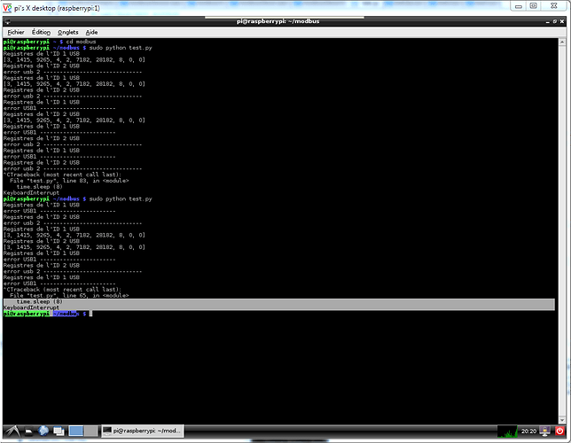
I tryed now with arduino library Modbus-Master-Slave-for-Arduino. and with this i can retrive respnse but i haveit only sometimes. see the attachement 1.

This is the arduino code for test:

/**
 *  Modbus slave example 3:
 *  The purpose of this example is to link a data array
 *  from the Arduino to an external device through RS485.
 *
 *  Recommended Modbus Master: QModbus
 *  http://qmodbus.sourceforge.net/
 */

#include <ModbusRtu.h>

// assign the Arduino pin that must be connected to RE-DE RS485 transceiver
#define TXEN	2 

// data array for modbus network sharing
uint16_t au16data[16] = {
  3, 1415, 9265, 4, 2, 7182, 28182, 8, 0, 0, 0, 0, 0, 0, 1, -1 };

/**
 *  Modbus object declaration
 *  u8id : node id = 0 for master, = 1..247 for slave
 *  u8serno : serial port (use 0 for Serial)
 *  u8txenpin : 0 for RS-232 and USB-FTDI 
 *               or any pin number > 1 for RS-485
 */
Modbus slave(1,0,TXEN); // this is slave @1 and RS-485

void setup() {
  slave.begin( 19200 ); // baud-rate at 19200
}

void loop() {
  slave.poll( au16data, 16 );
}

and this is my python code on RPi for test:

#!usr/bin/env python
from math import pi,sqrt,acos

import subprocess
import time
import RPi.GPIO as GPIO
import urllib
import httplib
import minimalmodbus
import time
import serial

instrument = minimalmodbus.Instrument('/dev/ttyUSB0',1) 	# Nom du port et adresse modbus // port série de raspberry = ttyAMA0 // port usb = ttyUSB0
instrument2 = minimalmodbus.Instrument('/dev/ttyUSB0',2) 	# Nom du port et adresse modbus // port série de raspberry = ttyAMA0 // port usb = ttyUSB0


instrument.serial.baudrate 					= 19200
instrument.serial.bytesize 					= 8
instrument.serial.parity 					= serial.PARITY_NONE
instrument.serial.stopbits 					= 1
instrument.serial.timeout 					= 1                		# secondes
instrument.mode								= minimalmodbus.MODE_RTU 	# rtu ou ascii // MODE_ASCII ou MODE_RTU
instrument.debug 							= False
instrument.serial.xonxoff					= True
instrument.serial.rtscts					= False
instrument.serial.dsrdtr					= False
minimalmodbus.CLOSE_PORT_AFTER_EACH_CALL	= True

instrument2.serial.baudrate 				= 19200
instrument2.serial.bytesize 				= 8
instrument2.serial.parity 					= serial.PARITY_NONE
instrument2.serial.stopbits 				= 1
instrument2.serial.timeout 					= 1                		# secondes
instrument2.mode							= minimalmodbus.MODE_RTU 	# rtu ou ascii // MODE_ASCII ou MODE_RTU
instrument2.debug 							= False
instrument2.serial.xonxoff					= True
instrument2.serial.rtscts					= False
instrument2.serial.dsrdtr					= False

usb1_on = True
usb2_on = True


if instrument.debug == True:
	print instrument

# Lecture d'un registre
while 1:
	if usb2_on == True :
		try:
	#		test_reg = instrument.read_register(1,0)		
	#		print test_reg
	#		test_reg = instrument.read_register(1,0)
	#		print test_reg
			print "Registres de l'ID 1 USB"
			test_reg = instrument2.read_registers(0,10,4)		# lecture plusieurs registres,( registre de départ, nb de registres à lire (max 10), décimales)
			print test_reg
	#		test_reg = instrument2.read_registers(0,2,3)
	#		print test_reg
			time.sleep (0.05)

			
		except:
			print ("error USB1 -----------------------")
			time.sleep (8)
		
		
	if usb1_on == True :
		try:
	#		test_reg = instrument.read_register(1,0)		
	#		print test_reg
	#		test_reg = instrument.read_register(1,0)
	#		print test_reg
			print "Registres de l'ID 2 USB"
			test_reg = instrument.read_registers(0,10,4)		# lecture plusieurs registres,( registre de départ, nb de registres à lire (max 10), décimales)
			print test_reg
	#		test_reg = instrument.read_registers(10,10,4)
	#		print test_reg
			time.sleep (0.05)
			
		except:
			print ("error usb 2 ------------------------------")
			time.sleep (8)

tankyou another time to help me and sorry for my english i'm french boy

Yep!

None of this modules need Modbus. Try simple message before adding complicated behavior. Thought it would normaly works as simple sérial things.

@+

Zoroastre.

For your RPi, look at using http://libmodbus.org/ as your Modbus library.
It can handle the Tx enable pin to control the data direction of RS-485 half duplex.


Paul

Hi Oxedgar,
Have you completed your project?
Could you please share to us how your solution to interconnect between RPi and Arduino?
Thanks in advance.

arwinkarsum:
Hi Oxedgar,
Have you completed your project?
Could you please share to us how your solution to interconnect between RPi and Arduino?
Thanks in advance.

this works for me, I used an usb rs485 adapter in raspberry and a CI max 485 in the arduino side.
rasp3

#!/usr/bin/env python

import subprocess
import time
import RPi.GPIO as GPIO
import urllib
import httplib
import minimalmodbus
import time
import serial

#diagnostic
#print(minimalmodbus._getDiagnosticString())
instrument = minimalmodbus.Instrument('/dev/ttyUSB0',1)#port name , slave address(in decimal)
instrument.serial.baudrate 					= 19200
instrument.serial.bytesize 					= 8
instrument.serial.parity 					= serial.PARITY_NONE
instrument.serial.stopbits 					= 1
instrument.serial.timeout 					= 1                		# secondes
instrument.mode								= minimalmodbus.MODE_RTU 	# rtu ou ascii // MODE_ASCII ou MODE_RTU
instrument.debug 							= False
instrument.serial.xonxoff					= True
instrument.serial.rtscts					= False
instrument.serial.dsrdtr					= False
#minimalmodbus.CLOSE_PORT_AFTER_EACH_CALL	= True
##
instrument2 = minimalmodbus.Instrument('/dev/ttyUSB0',2)#port name , slave address(in decimal)
instrument2.serial.baudrate 					= 19200
instrument2.serial.bytesize 					= 8
instrument2.serial.parity 					= serial.PARITY_NONE
instrument2.serial.stopbits 					= 1
instrument2.serial.timeout 					= 1                		# secondes
instrument2.mode								= minimalmodbus.MODE_RTU 	# rtu ou ascii // MODE_ASCII ou MODE_RTU
instrument2.debug 							= False
instrument2.serial.xonxoff					= True
instrument2.serial.rtscts					= False
instrument2.serial.dsrdtr					= False
minimalmodbus.CLOSE_PORT_AFTER_EACH_CALL	= True
## read temperature
temperature=instrument.read_register(2,1)#register number, number of decimals
print ("temp1:",temperature)

temperature2=instrument2.read_register(1,1)#register number, number of decimals
print ("temp2:",temperature2)

arduino uno

/**
 *  Modbus slave example 3:
 *  The purpose of this example is to link a data array
 *  from the Arduino to an external device through RS485.
 *
 *  Recommended Modbus Master: QModbus
 *  http://qmodbus.sourceforge.net/
 */

#include <ModbusRtu.h>

// assign the Arduino pin that must be connected to RE-DE RS485 transceiver
#define TXEN  4 

// data array for modbus network sharing
uint16_t au16data[16] = {
  3, 'A', 9265, 4, 2, 7182, 28182, 8, 0, 0, 0, 0, 0, 0, 1, -1 };

/**
 *  Modbus object declaration
 *  u8id : node id = 0 for master, = 1..247 for slave
 *  u8serno : serial port (use 0 for Serial)
 *  u8txenpin : 0 for RS-232 and USB-FTDI 
 *               or any pin number > 1 for RS-485
 */
Modbus slave(2,0,TXEN); // this is slave @1 and RS-485

void setup() {
  slave.begin( 19200 ); // baud-rate at 19200
}

void loop() {
  slave.poll( au16data, 16 );
}

/quote
this works for me, I used an usb rs485 adapter in raspberry and a CI max 485 in the arduino side.
rasp3
/unquote

Hi Pods,
Glad to hear your success story..!
As me a new comer for RPi and Arduino, it seems difficult to be followed.
I have purchased the usb rs485 for both RPi and Arduino, instad of IC max458 on Arduino side.
But, I haven't tried to program it.

I will update if I have tried it.

arwinkarsum:
Hi Pods,
Glad to hear your success story..!
As me a new comer for RPi and Arduino, it seems difficult to be followed.
I have purchased the usb rs485 for both RPi and Arduino, instad of IC max458 on Arduino side.
But, I haven't tried to program it.

I will update if I have tried it.

any news ?