I have a working code which runs similar oled but with SSD1306. With first line on and SSD1306, it works. Second line on, with SSD1309 doesn't. I have soldered R15 and R13 which are supposed to turn on I2C, but I am not even sure if library supports SSD1309 in I2C mode.
david_prentice:
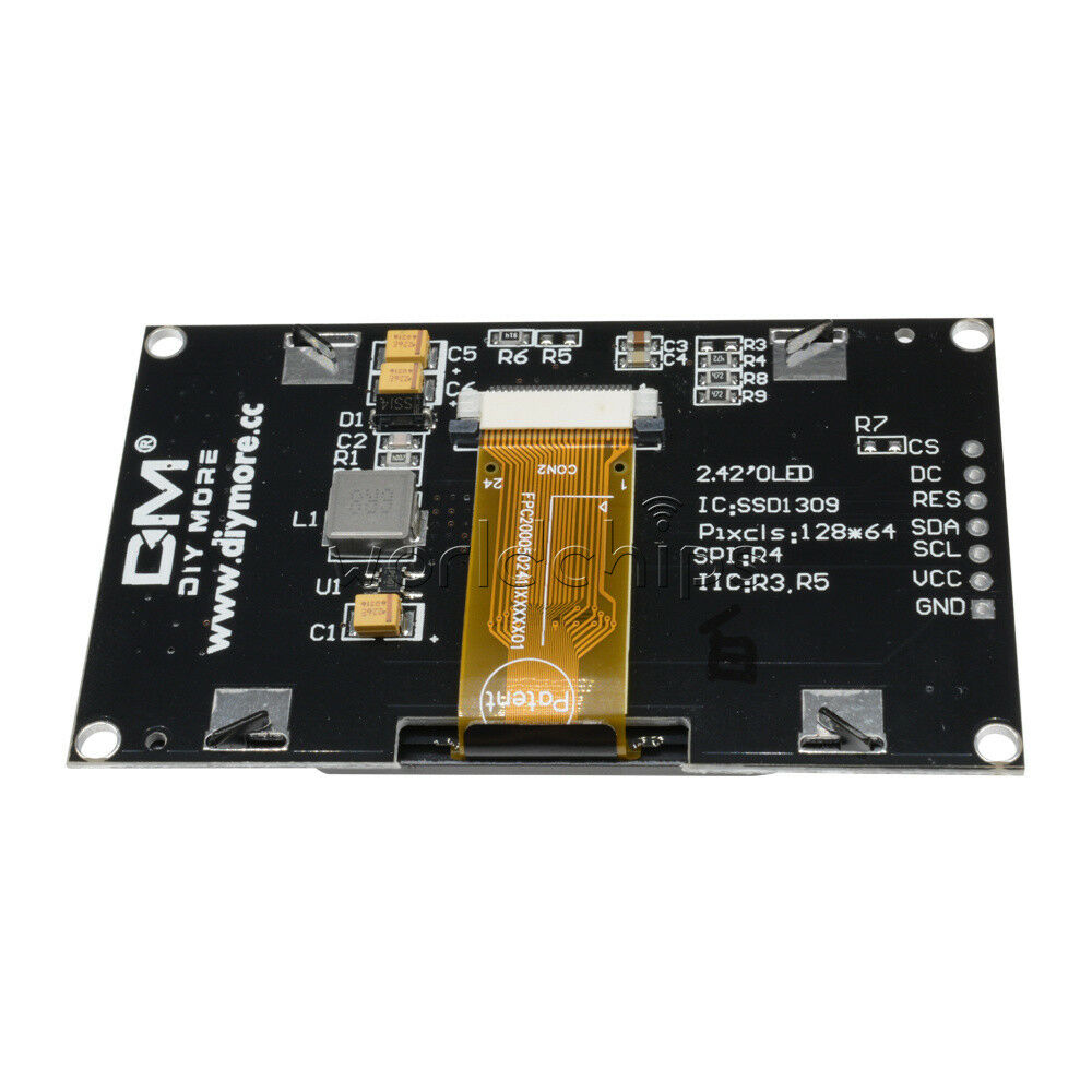
I2C should work fine. You remove R17. Solder links on R13, R15.
Make sure that you connect RES and DC. DC selects I2C address 0x3C or 0x3D. Specify the RES pin in the constructor.
If you are tight for GPIO pins, just add pullup to RES pin. (there might already be pullups on the pcb for RES, DC. Test with a DMM)
Seriously. If you have a problem, you should describe it properly.
David.
I have already removed R17 and soldered two resistors at R13 and R15. I have now shorted DC and RES, and pulled them up with 10K to VCC. Still nothing on I2C scanner. I have two displays (not connected at the same time), neither recognized on I2C bus. MCP23008 on the same bus is responding just fine.
Weird thing is, if I keep some pressure on the middle of the board, intermittently I get a response from 0x3D. Because of this, I ordered second OLED, which behaves the same way.
I certainly would not "short" DC or RES. You either pullup to 3.3V or pulldown to 0V with resistors. Then the pins are still usable for program control if you want to.
R13, R15 should be 0R. But anything less than about 470R should be ok.
Early SSD1306 displays did not connect LCD_D1 to SDA pin when configured for I2C.
I presume that that is what R13 is for. You can trace the pcb. My eyesight does not want to do it for you.
You have several posts under your belt. I would have expected you to use more accurate descriptions e.g. values for R13, R15. What is "short"?
david_prentice:
I certainly would not "short" DC or RES. You either pullup to 3.3V or pulldown to 0V with resistors. Then the pins are still usable for program control if you want to.
R13, R15 should be 0R. But anything less than about 470R should be ok.
Early SSD1306 displays did not connect LCD_D1 to SDA pin when configured for I2C.
I presume that that is what R13 is for. You can trace the pcb. My eyesight does not want to do it for you.
You have several posts under your belt. I would have expected you to use more accurate descriptions e.g. values for R13, R15. What is "short"?
David.
Thanks, we are getting somewhere. I assumed that R13 and R15 should be the same value as R17. Now I have replaced both with 0R. I also pulled RES with 10K up to Vcc, and I am getting response from 0x3C. Should it be pulled with lower value?
Nothing yet on the screen though. At some point I got something, but not sure which combination of params was it.
U8GLIB is too slow over I2C so I was hoping that SSD1306Ascii could be made to work with it.
I2C is not unreasonable. I would use Adafruit_SSD1306 library first. But I am sure that u8g would be fine too.
First step is to check DC. Does it have an existing 10k pulldown on the pcb? It is essential that DC has a stable value. Otherwise it will not know whether it is 0x3C or 0x3D.
As a general rule, a 128x64 monochrome is always going to be fast. There is only 1kB of data to repaint the whole screen.
Just wanted to add to this. I have the same OLED and cannot get it to work over I2C. It works perfectly on SPI using this construct when wired as shown above:
U8GLIB_SH1106_128X64 u8g( 13, 11, 10, 9, 8 );
When using the SSD1309 or SSD1306 driver the display is shifted and does not work correctly. I removed the resistor from R17 and added a solder jumper on R13 and R15 as detailed.
If somebody has this working on I2C with U8GLIB I'd like to know what magik you invoked.
Just wanted to post on here that these displays do work in I2C mode at address 0X3C
I had to solder a 10K resistor between pins Vcc and RES (I just soldered it on the Display side of the connector) and remove the R17 resistor and jumper R13 and R15, but other than that it just worked...I'm using the U8G2 liobrary and using constructor:
for U8G2
U8G2_SSD1306_128X64_NONAME_F_SW_I2C u8g2(U8G2_R0, /* clock=/ SCL, / data=/ SDA, / reset=*/ U8X8_PIN_NONE); // All Boards without Reset of the Display (SPI I2c IIc Ebay boards)
or for U8Glib
U8GLIB_SSD1306_128X64 u8g(U8G_I2C_OPT_NONE|U8G_I2C_OPT_DEV_0); // I2C / TWI
I already have a project that works well with the U8X8_SSD1306_128X64 library and 0.96" displays.
Removed R4 , jumped R3, R5
So far: I added the usual I2C Pullups and connected to an Arduino configures for the before mentioned 0.96"
also tried to pullup RES (2k2) , pull up/down the DC (for address selection)
no success.
So I compiled it with RES support, and tried with , and without an 3k3 pullup for RES (to bring it up before arduino boots)
I already have a project that works well with the U8X8_SSD1306_128X64 library and 0.96" displays.
Removed R4 , jumped R3, R5
So far: I added the usual I2C Pullups and connected to an Arduino configures for the before mentioned 0.96"
also tried to pullup RES (2k2) , pull up/down the DC (for address selection)
no success.
So I compiled it with RES support,(connected RES) and then tried with , and without an additional 3k3 pullup for RES (to bring it up before arduino boots)
In my case display didn't respond (I thought it could be already dead) until I've connected reset pin to ESP8266 reset pin. If I disconnect it while it is working the screen turns off.
Also, somewhere was mentioned that instead of connecting reset pin to reset you could connect display reset pin to GND via resistor (10 kOhm or greater) and than to some digital pin of your board, so get reset pin low on startup and manually set pin high before lcd init cal)
Not sure what is better for R5: shortcut or resistor (4.6 kOhm similar to others), but shortcut works ok and it is easier to make.