I recently got an MSGEQ7 IC for my music reactive LED project. The wiring according to the datasheet worked perfectly and the circuit was working so far. I always used my PC speakers for testing and never had any issues. However, I currently cannot use them and decided to use my Bluetooth speakers for testing. I was surprised to see that it did not work at all, there was no data output on any channel (I'm using the MSGEQ7 library by NicoHood and the noise reduction).
I soon found out why it was not working. I did not have the GND of my Audio Jack connected to the ground of my ESP32 board. After I connected it to the GND pin it seemed to work fine. But now I have a different issue. I'm using an aux splitter cable and am hooking one end up to the speakers, the other one is connected to the audio jack on the breadboard. When I connect the GND of the audio jack to the pin of the ESP32 there is a constant audible noise on my speakers which gets really annoying, especially if there is no sound and the LEDs are idling.
Wiring of MSGEQ to my ESP is according to the datasheet. The pins are connected as following:
STROBE -> D33
OUT -> D34
RESET -> D32
The ESP32 is currently powered by USB power. When the project is in a more final state I will power it from my 5V LED power supply. (This is the esp module I'm using)
Is there any way I can get rid of the noise on the audio jack?
Thanks for your reply. I hope this will help getting rid of the noise. I did some searching and this star wiring seems not like a very beginner thing to do. Do you know any easy to follow guides for beginners like I am? Would really appreciate it.
I did some searching and this star wiring seems not like a very beginner thing to do.
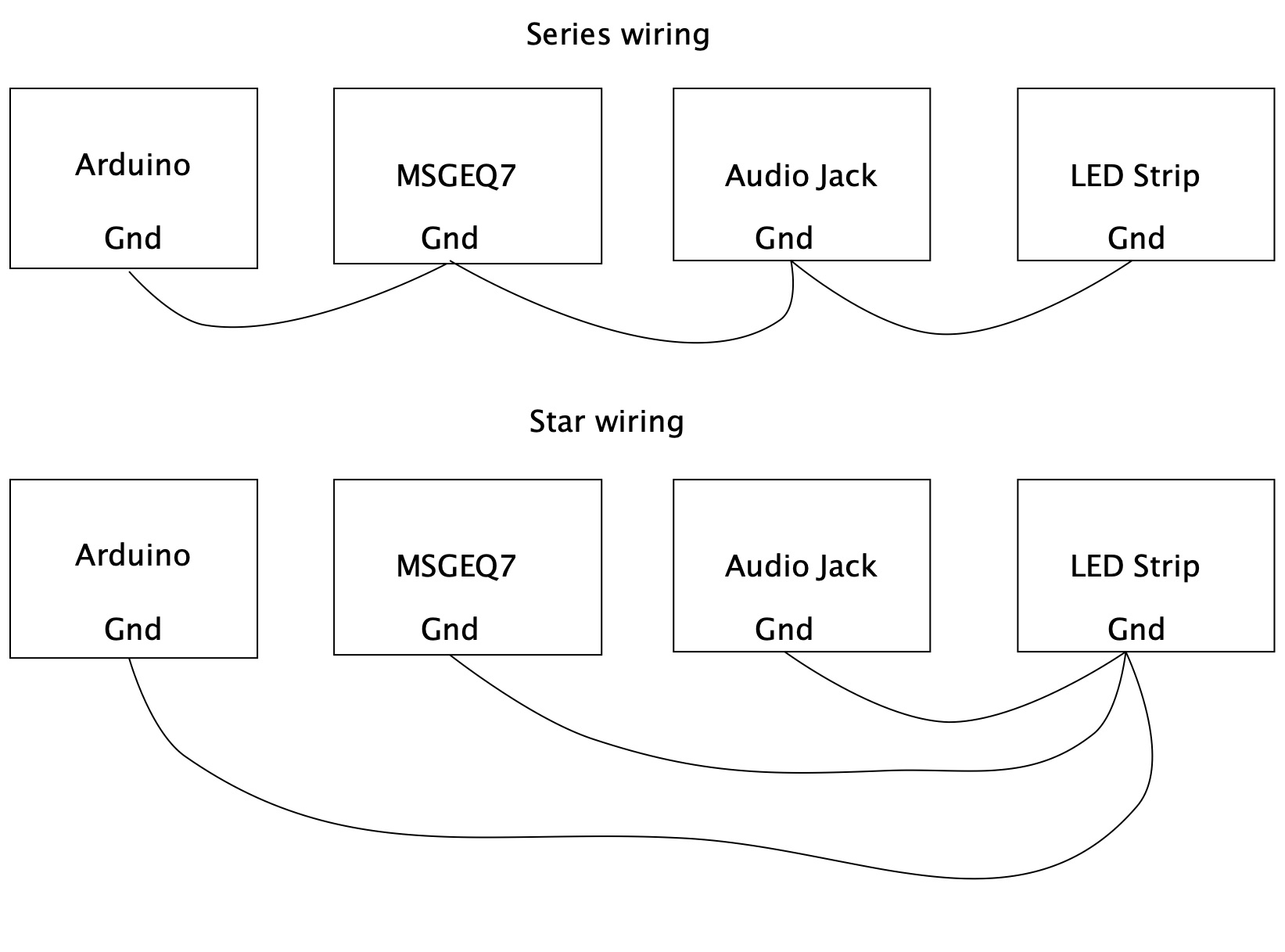
What? I think you are not understanding what it means. It means wiring all the grounds physically to the same place instead of chaining them. Like this:-
Oh sorry, the articles I found were from some audio magazine and were going really in-depth, so I got really confused. However, this is actually the way i wired everything up. I joined all ground pins in a single row of my breadboard and then made a ground connection to my power supply. However, this is the wiring that introduces the noise. Or did I get anything wrong?
I joined all ground pins in a single row of my breadboard
Yes but that is not star wiring is it.
The whole point of star wiring is that all the ground currents do not flow through the other components. By having them all on the same row you can still have the ground currents from for example from the LEDs flowing through the audio circuits and causing what is known as ground bounce.
So can you post a proper diagram and a photograph of your setup. Both please, one on its own is not much use.
I don't know if this will work for you but I had similar "ground loop noise problem" with some sound-activated lights in my van. (I'm not using an MSGEQ7.)
I solved the problem by adding a resistor between the audio-signal ground and the Arduino-input ground. In my setup I have an RCA connector like [u]this[/u] going into the Arduino box, so there's a resistor soldered to the ground tab instead of a direct connection to ground.
Now.... Since there is a power-ground and apparently an apparently an actual ground loop, I'm not sure why I didn't just leave that ground connection open... I really don't remember if I had a reason for that...
This sort of thing is called a “ground lift” resistor. It is used a lot in effects pedal which can make running lots of peddle off one power supply a problem, what happens is these resistors can fry. But only having one might work.
I think I used 1K or 10K so that can't happen (with a 12V power supply). This is only the audio ground. The "power" has it's own ground (and that's why there is a ground loop in my setup. )
Hello, I have also noise in the end of the spectrum in High Frequencies, can you please tell me what I did wrong?
I used 22K 2Watt Resistor on audio jack instead of, I hope, should be 1/2 Watt. or? Does it matter here?
I used thin wires, just wanted to try if my circuit will work, planning to switch all wires for thicker. Any of those should be even thicker or somehow shielded?
I used 470R 2Watt resistor for output data to my LED strip.
I already soldered all ground wires to 1 spot... didn't helped, nothing changed...
Powering from 5V 4A power supply or USB makes no difference.
Thanks for every tip.
NOTE: I need to raise floor level (0,1023,0,255) from 0 to 150 to filter out noise so now my settings in arduino are mapped (150,1023,0,255) but this is now what I want to do, reduce noise via code...
Messing about with the map function will not help, the low noise still gets through. You need to use subtraction or an if statement to remove low level noise.
We can only tell you what you did wrong if you tell us what you did.
Having said that, you will still get some noise picked up at the high end because you have dropped into analogue electronics in a digital environment.
So you are saying, I can't get rid of the noise, it's normal? So I need to raise floor level, that's the only way? Or raising from 0 to 150 it's too much noise in my circuit?
What about this one? : I connected everything like on schematic, except 100nF Capacitor under SI5351 between GND and VIN...
Do i need that one, looks like there is one on the far right that already do the job? or?
No the capacitors used for the audio path should not be ceramic.
So you are saying, I can't get rid of the noise, it's normal?
Yes, some degree of noise is normal. You can minimise it by using proper components and proper layout and supply decoupling. Still not see your schematic or a picture of how you constructed it.
Do i need that one, looks like there is one on the far right that already do the job
Up to you, do you want to minimise the noise or not? Your choice.
Grumpy_Mike:
No the capacitors used for the audio path should not be ceramic.
I was thinking opposite from what you wrote... my bad... so I used the right ones...
Yes, some degree of noise is normal. You can minimise it by using proper components and proper layout and supply decoupling. Still not see your schematic or a picture of how you constructed it.
What a dogs breakfast that is. I would be ashamed to present that as a video. It is an appalling technique. First off you only put the chip into a socket once the socket is soldered onto the board. Then he is using the wrong sort of capacitors for decoupling. The capacitors across power and ground have to be ceramic otherwise they are not much use.
The power supply is totally inadequate for driving that many LEDs and the wire routing is bad. There is no large capacitor across the LED strip and that PCB is not designed for good isolation.
The whole thing is just left in separate bits and soldering to a pin while it is plugged into an Arduino header pin is bound to cause heat damage.
Sadly yet another example of someone posting something on the internet who doesn’t know what he is doing.
Yes it is two chips but these are only second order filters so it is not very good at separating the spectrum into 14 channels. There is too much overlap.
It is not your fault but people like him make me very angry.
Except all the faults he made (I didn't soldered chip inside socket, I put them inside before connecting power).
What could be source of noise in that project? He doesn't have any noise in the video
Change to ceramic capacitors? which ones? 100nF or 10nF ?