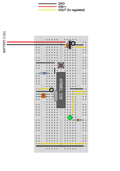
ok..stuck at work.. dont have my real circuit here..
so I mocked one up in photoshop to mirror my current circuit layout.
Labels:

No labels:
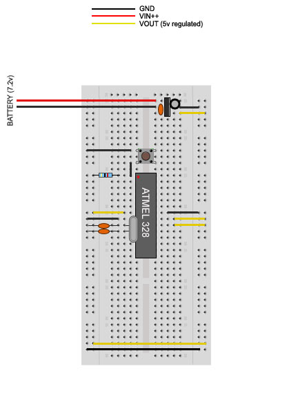
so I can work on it a bit while...at work. LOL
at least be able to communicate and visually display my interpretation
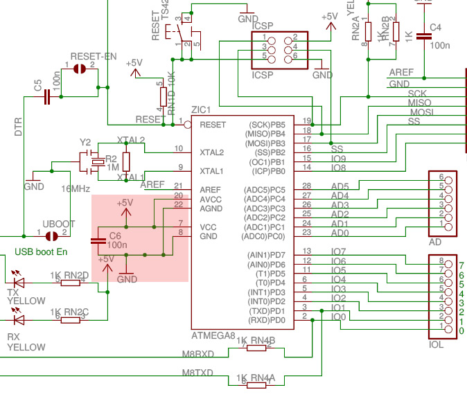
OK..I checked out .pdf as you suggested..
found the C6 portion.. (but being so new I cant 'just wire it up the same way' unfortunately)
Im a bit confused....
1.) as to 'WHY' this is needed....
2.) why this isnt/wasnt included on these barebones/minimal Arduino clone/circuit tuts I see all over?
(and still a bit un-clear on this series resistor comment you made.. just want to ensure I am doing thing proper..a bit hard when Im 'following' at this point.. =( ..however I do appreciate your help/advice.. gotta sink in eventually) =)
so on the diagram posted (C6)..
I see there is/are other lines/traces tied into this 100nF cap across the VCC & GND pins?
Is this something I need to deal/worry about? Kind of confusing..(the diagram)
Your suggestion. is it as easy as just putting a 100nF cap across pins 7 (VCC) & 8 (GND)?
after the I/O pins..before the jumper wires, tying into the rails?
(still unclear as to what to do with those other lines 20 (Avcc) & 22 (GND) ??
(and again..my brain is stuck trying to figure out/worry about this series resistor you mentioned?)
when thinking about.. I think your just saying.. ALWAYS USE A RESISTOR on LEDS like that?..
"OR" are you saying.. I need to have this series resistor as part fo the circuit for other reasons? as a base part of the Arduino 'circuit' itself.. regardless of the leds or other external components that may be used?
In the end.. I will implement the rule of 'always use a resistor'.. but I dont want to confuse myself on what is required to build the base circuit.. and what is needed for when I add 'blinkies/buttons'..etc..
to wrap up even more confusion.. LOL..
I am a bit confused on this:
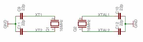
2 different (same) crystal wiring diagrams?
looks to be mechanically the same? (same resistors used...same layout?)
but the name for the xstal is different?
That I need any more confusion..LOL.. but it was bugging me?!
Thanks
update:
ok.. here I am trying to implement both of you comments/suggestions.. (hoping Im correct)
adding the led..and resistor to it.. as well as adding the 100nF cap to the VCC & GND on the left side of chip.
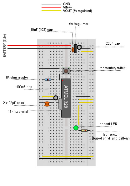
any/all feedback is appreciated.
thanks guys.