I'm doing a project with Arduino and I have problems, I hope you can help me.
My idea is to create a system to the management of my turtle water tank. I begin creating a simple part of the project with a sensor to alert me when the water level is low. If this happens I activate the motor to put water inside the tank again.
I know that I can do this without arduino but I will put more logic in the future.
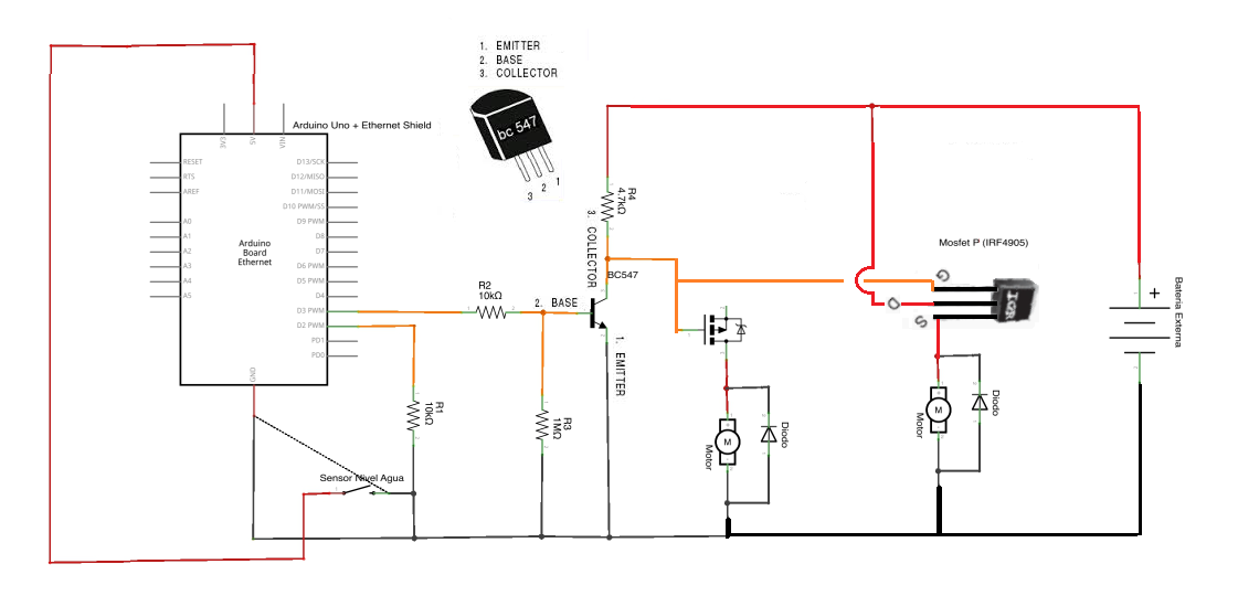
I create a circuit but something is wrong. (image attached)
Transistor BC547 to control the Gate of the Mosfet
The battery (6 AA) 9V
And a Diode to avoid reverse current.
I don't know why but the motor is very slow and the mosfet is very hot. I measure and the battery has 8,30V but in the motor I have 1,80V. The current is aprox 1,2A.
I don't have sink in the mosfet but I think that this is not my main problem.
I'm new in electronic and I can't understand what is happening.
Your circuit seems okay, but the mosfet should not get hot. Perhaps the source and drain are exchanged.
Can you use a 'logic level' n-channel mosfet ? With that you don't need the extra transistor so the circuit is simpler and less chance for error. The motor/pump with diode connected to the + side of the battery.
I hope you don't use PWM for the mosfet, only a simple on and off.
The sensor and motor are very cheap. You have to test them how long they will last. Perhaps a day, perhaps a few years.
Can you measure the current for the motor without the mosfet ? So you know the current that motor requires.
IRF4905 is 20mOhm mosfet, so at 1.2A there should be 24mV voltage drop and 29mW of heat.
Either is misconnected or damaged or both.
Disconnect motor and troubleshoot with friendlier load that would not damage IRF even if misconnected, e.g. 12V/2W bulb. Make sure BC547 is switching. Then make sure IRF4905 is switching. When this is all working, connect motor.
luisilva, when drain and source are swapped, should not this MOSFET function as schottky? Why high voltage drop then ?
luisilva:
You don't need the diode. The diode is inside the MOSFET.
You need a fly-back diode over an inductive load. Always.
In some cases a filter is used, but I would still recommend the fly-back diode.
If you want to do it right, you need a fast diode like the UF4007. An 1N4007 is only for 50/60Hz mains rectifier and could be too slow for a fast mosfet.
marioqn:
I put the diode because I previously burn out an H-Bridge and I have fear
But my question is: The diode has correct orientation? Maybe, If the diode is reverse maybe it can do the motor get low voltage.
Per your diagram the orientation and placement is correct and yes it is required. The mark on the diode will be on the side of the positive connection on the motor.
Assuming that mosfet is G D S when I put the motor without load (no water flow) I have in DS and GD -4V but when I put water to flow I have -2 V aprox in both.
The same voltage is across the diode.
In BC547:
I think the problem is here because Arduino provide 5V aprox and the center pin (V divisor) has 0,65V so, I think mosfet is not working because of this.
The left pin have 9V battery entry with a 4,7K ohm resistance (aprox 8,2V in pin). This pin is connected with left mosfet pin.
The center pin have 5V arduino input with a voltage divider with 10k and 1M ohm resistances. In the pin I have 0,65V.
The right pin is set to Ground.
The center pin must output 4,95V with the V-Divider formula.
dave-in-nj:
this was MUCH more informative
Thanks dave-in-nj and sorry, My english is bad and the picture is too much for me :S