And this is the bare bones of my actual full script.
It reads 8x8 Mux channels and sends them over serial to Hairless.
I had actually found the serial.write solution (credited) yesterday afternoon, but had forgotten to send myself it...
There's probably some unused bits and potentially a bit more tidying up to do..
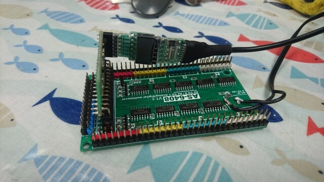
The board I am using is fantastic, packing the 8x8 mux and an arduino together with no additional interconnection needed.
Cheers
TT
/* ====================AS-6408 Demo code====================================
// Credit inhaos + TwinTurbo
 www.inhaos.com

 Hardware: AS-6408: 64 to 8 or 64 to 1 Analog Digital Multiplexer
           http://www.inhaos.com/product_info.php?products_id=154

           UNO CORE: Arduino UNO CORE with ATMega328P
           http://www.inhaos.com/product_info.php?products_id=143
===========================================================================*/


//Port definitions
int ctr_A = 6 ;
int ctr_B = 8 ;
int ctr_C = 10 ;

int sig_Ctr_A = 5 ;
int sig_Ctr_B = 7 ;
int sig_Ctr_C = 9 ;


#define APP_RECV_BUFFER_SIZE      100

int App_RecvLen = 0;
bool App_RcvdFirstFlag = false;
bool App_RecvFinishFlag = false;
char App_AckCommand = 0;
char App_RecvBuffer[APP_RECV_BUFFER_SIZE];
int AdcDataArray[8];
int mux = 0;
int muxchan = 0;

void setup() {
  // put your setup code here, to run once:
  Serial.begin(9600);

  //Initialize control ports
  pinMode(ctr_A, OUTPUT);
  pinMode(ctr_B, OUTPUT);
  pinMode(ctr_C, OUTPUT);
  pinMode(sig_Ctr_A, OUTPUT);
  pinMode(sig_Ctr_B, OUTPUT);
  pinMode(sig_Ctr_C, OUTPUT);

  digitalWrite(ctr_A, HIGH);
  digitalWrite(ctr_B, HIGH);
  digitalWrite(ctr_C, HIGH);
  digitalWrite(sig_Ctr_A, HIGH);
  digitalWrite(sig_Ctr_B, HIGH);
  digitalWrite(sig_Ctr_C, HIGH);

  //Adc ports initialize
}

void loop() {
  // Set the Mux
  // Set a varialble for that
  // Read the mux/send the data over MIDI
  // Delay
  // Repeat for all MUXES.
  // Note, this can be put in a loop but it's shown here as WORKINGS

  //This sets the mux we are going to use out of the 8 available on the AS6408
  // call function SetChn(1)
  SetChn(1);
  // set a variable of mux for later use.
  mux=0;
  // read the mux lines using the function ReadAdcAll()
  ReadAdcAll();
  // Put in a little delay
  delay(200);

  // Repeat for the other 7 mux's
  mux=8;
  SetChn(2);
  ReadAdcAll();
  delay(200);
  mux=16;
  SetChn(3);
  ReadAdcAll();
  delay(200);
  mux=24;
  SetChn(4);
  ReadAdcAll();
  delay(200);
  mux=32;
  SetChn(5);
  ReadAdcAll();
  delay(200);
  mux=40;
  SetChn(6);
  ReadAdcAll();
  delay(200);
  mux=48;
  SetChn(7);
  ReadAdcAll();
  delay(200);
  mux=56;
  SetChn(0);
  ReadAdcAll();
  delay(200);
  }

boolean SetChn(int chn)
// SetChn sets the 3bit Multiplexer selection on the 6408 out of the 8 available Muxes.
// using the value passed by SetChn in the void loop.
{
  switch (chn)
  {
    // if the value passed from the void loop is zero we set the 3 pins DigitalWrite High, and then stop
    // further processing with a break.
    case 0:
      digitalWrite ( ctr_A , HIGH ) ;
      digitalWrite ( ctr_B , HIGH ) ;all the A0-A7
      digitalWrite ( ctr_A , HIGH ) ;
      break;
   // Do the same for the other values passed, altering the 3 bit binary state of the pins to select the muxes...
   //
    case 1:
      digitalWrite ( ctr_A , HIGH ) ;
      digitalWrite ( ctr_B , HIGH ) ;
      digitalWrite ( ctr_C , LOW ) ;
      break;
    case 2:
      digitalWrite ( ctr_A , HIGH ) ;
      digitalWrite ( ctr_B , LOW ) ;
      digitalWrite ( ctr_C , HIGH ) ;
      break;
    case 3:
      digitalWrite ( ctr_A , HIGH ) ;
      digitalWrite ( ctr_B , LOW ) ;
      digitalWrite ( ctr_C , LOW ) ;
      break;
    case 4:
      digitalWrite ( ctr_A , LOW ) ;
      digitalWrite ( ctr_B , HIGH ) ;
      digitalWrite ( ctr_C , HIGH ) ;
      break;
    case 5:
      digitalWrite ( ctr_A , LOW ) ;
      digitalWrite ( ctr_B , HIGH ) ;
      digitalWrite ( ctr_C , LOW ) ;
      break;
    case 6:
      digitalWrite ( ctr_A , LOW ) ;
      digitalWrite ( ctr_B , LOW ) ;
      digitalWrite ( ctr_C , HIGH ) ;
      break;
    case 7:
      digitalWrite ( ctr_A , LOW ) ;
      digitalWrite ( ctr_B , LOW ) ;
      digitalWrite ( ctr_C , LOW ) ;
      break;
    default:
      return false;
      break;
  }
  return true;
}

void ReadAdcAll()
// Reads through the 8 mux channels on the selected mux and and initiates the message send.
{

  // Read the Mux to an array
  // Variable for the mux channel to read 0-7
  int i;
  // variable for the value read from the mux 0-1023
  int y;
  // loop through values 0+1+1... until i = less than 8
  for(i = 0; i < 8; i++)
  {
    // fill and array the value i and the value read from Analoug A0
    AdcDataArray[i] = analogRead(A0 + i);
  }
;
  // we could actualy do away with this and the array above all together...
  // read the array and call the Serial Write.
  for(i = 0; i < 8; i++)
  {
    // Analog 1023 to MIDI 127 conversion
    // The output of the analogue read is from 0-1023, Midi understands values 0-127 . So divide the analogue value by 8
    y = AdcDataArray[i]/8;
   // the value mux was set int the main void loop,
   // we add this to i to get the correct channel in the range 1-64
   muxchan = mux + i;
   // We then send 3 values to the MIDImessage function
   // 191 we know is the CC value for the continus controller.
   // muxchan we have set above to specifiy the channel we are working on
   // y is the value determined from the mux read and division above.
    MIDImessage(191, muxchan, y); //pass values out through standard Midi Command
     }
  }


void MIDImessage(byte command, byte data1, byte data2) //pass values out through standard Midi Command
// Credit https://tttapa.github.io/Arduino/MIDI/Chap04-MIDI-Controller.html
{
   //write the values provided from ReadAdcAll above..
   Serial.write(command);
   Serial.write(data1);
   Serial.write(data2);
}