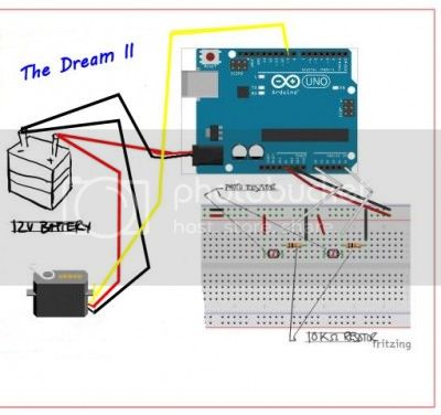
Looking for some help in regards to making this project safer and more powerful. Basically the set up has 2 light sensors feeding back information to an Arduino one . The servo will rotate left or right depending which light sensor is receiving more light or remain still if the light sensors are of equal value. The circuit is working properly as u can see in the YouTube video link lower down. ...but here's the questions
could this be better setup?
does the circuit need a diode? if so where and what kind?
how does one go about upgrading it to a 12v servo and 12v power supply?
I find it almost impossible to figure out wiring arrangements from that "photographic" type of picture. A drawing of the connections is easier to understand - post a photo of the drawing.
You haven't identified the components in the picture.
How is the Arduino powered?
Those 9v batteries are a terrible source of power. They can't produce enough power and they run down too quickly.
Assuming everything is working at 5v and that the unnamed IC is a 7805 voltage regulator then it should be OK just to replace the 9v battery with the 12v power supply.
Note that you don't convert a 5v servo to a 12v servo. You "convert" the 12v to 5v so it can power the servo safely.
A 12V servo has a 12V supply, you still route ground and signal to the Arduino to
control it. In other words the 12V and 5V supplies share a common ground, preferably
at a single common point (such as at the servo).
Grumpy_Mike:
That a servo has electronics in it and even if you could supply the motor with more voltage independently it would then get too hot and burn out.
That's true if you supply a 5v servo with 12v. But not if you have a 12v servo.
..plus i just found out that the 12v servo is digital!!!
It would want to be gold-plated at that price. I will stick to $5 5v servos.
That's true if you supply a 5v servo with 12v. But not if you have a 12v servo.
True but you would be rather silly running a 12V servo off 5V, it might not even work. Where as a stepping motor can be run to advantage off any high voltage providing you keep the current down to the limits. Even a resistor to limit the current will give you an increase in the potential top speed.
It would want to be gold-plated at that price
Well it has got a processor embedded in it so it runs with the minimum of overhead from the Arduino. It also has RAM and EEPROM in it. But having said that it does loop pricy.
That servo is not a standard R/C type servo, but rather one that uses serial communication to command the servo(s) attached to a serial bus via a serial protocol that includes a servo device ID, such that several servos can share a common "daisy-chained" bus that supplies data and power to the servos. It is no way compatible with the arduino standard servo library so cannot be used as you have proposed wiring to a arduino. I suspect that these are really just 5 volt servos that have built in +5 vdc voltage regulators inside the servos.
Grumpy_Mike:
True but you would be rather silly running a 12V servo off 5V, it might not even work. Where as a stepping motor can be run to advantage off any high voltage providing you keep the current down to the limits. Even a resistor to limit the current will give you an increase in the potential top speed.
Never mind. We are each talking about different things.