I need to speed control a 12 amp 24 voltDC compressor using an Uno, PWM pin. I have been looking for something akin to the TIP120 but capable of 15 or more amps.
There are several webpages that go into the maths but the mists decend and I'm not qualified for this sort of analysis.
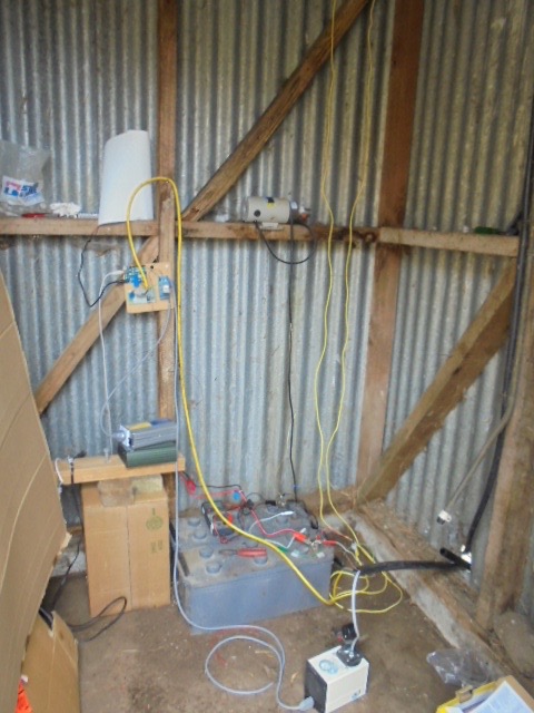
The application is to alternate between running an air compressor supply line into a 30 liter water tank. The air pushes water out of the bottom of the tank out to our farm 5000 gal tank. After 5 min, the air line vents to ambient and the 30 liter water tank fills by syphon 12 minutes.
The problem is the PV supplied compressor needlessly draws the full 12 amps from the battery/PV supply. I need to use PWM to back off on the supplied current. I need to experiment with this until I can balance the drain from the air pump motor with the input from the PV.
The pressure at full noise goes up to 38 PSI. I only need a fraction of that to move the water through the lines. IOW there is virtually no head, just 700 meters of 20 mm plastic pipe.
But I dont know what would be a good transistor for this design. I think a mosfet but the 510/520 data sheets say 10 amp absolute max drain-source continuous current...from there I just get more confused.
the need is getting urgent, we are at a summer long drought.
RECAP: I need a PWM control-able power transistor to vary the current to a 12 amp 24 volt DC motor
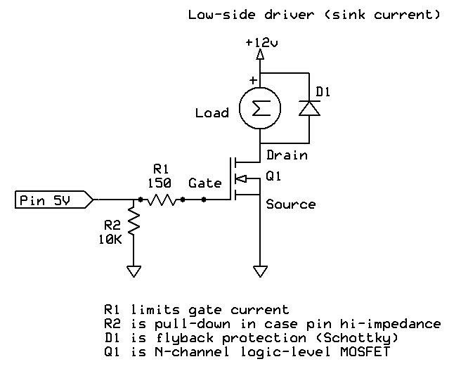
One thing that may be an issue - if you run it at a lower pressure, you have a lower flow rate and any sediment that ends up in the tank and out into the line may start plugging the line up. You may need to have that much pressure (maybe only once a day?/week?) to make sure the line does not get filled with sediment. The other consideration with the FET is they are "logic level" (that is the "L" in the number) - that level is assumed to be 5v logic not a board running at 3.3v (look at the gate voltage vs the Rds or voltage from source to drain in the data sheet for that transistor).
Vunderbar, thanks again. the devils in the detail. The circuit really takes out the guesswork and I'm trying to make this a durable system.
Larry, two questions
Does that diode need to be a shottkey? I've got some high amp rectifier diodes that I put across the PV Panel ...ok for this?
Is a 0.1uF ceramic cap in parallel with that diode a good idea?
gpsMikey, Good suggestion. I will build in a regular flushing cycle(s) at max pressure to prevent buildup. You are right, this is beautiful sweet spring water but i does have a fair bit of fine grit. I keep thinking about fashioning a sediment bulb of some sort.
Now my understanding (such that it is) is Uno DIO pins are at 5 V when logic HIGH. So I'm not sure what your comment ...Oh, some boards are run on 3.3 volt...is that what your warning is? mine is definely 5V. I'm using a little PV phone battery charger to supply it via usb port.
Procyan:
2. Is a 0.1uF ceramic cap in parallel with that diode a good idea?
Probably. Suppresses some commutator hash.
Procyan:
tried to attach/insert photos but not working
That's because you did not insert links to photos, you tried to insert Web pages as images.
You need to first find the URL of the image on the Web page - often tricky with those bodgie "hosting" sites which insist on inserting advertising everywhere - and make that an image link.
You are talking about a transistor heatsink(you provided a link!)
Ask yourself a question
if you drop 24V across the transistor then what is the load going to run off?, its not going to work so clearly according to your calculations somethings up
300W in an enclosure LMAO!, is this a titanium enclosure?
15 times 24 was 360 when I went to school anyway!
Edit
To quote yourself, learn electronics and learn to read a datasheet
This part really helps
Drain-Source On-State Resistance 0.11 max
Maybe I should demand Karma now ey haha LMAO, theres no shaming some people is there haha LMAO
The IRL540 is a fairly elderly and poor performing MOSFET, 77 milliohms. That's 11W at 12A, and
the Vds of 0.9V detracts from the 5V of gate drive, meaning Vgd would be only 4V or so when on,
perhaps increasing Rds(on)
Choose something at or below 10 milliohms and you'll have much lower heat dissipation (a fan
won't be needed, for instance). Don't bother with a 100V device, 40 or 50V rating should be
adequate (and much easier to find a low Rds(on) figure - high voltage MOSFETs compromise
on resistance a lot)
Good point.
Heatdink calvulations should be the same as power resistor calvulations:
R= 0.12 ohm
I= 15A
V(R) = 0.11 ,* 15 = 1.65V
P(R)= I * V = 15A * 1.65V
= 15A * 1.65V
= 24.75 W
(still higher than your results)
Using YOUR junction resistance I might add.
Thanks for the tutorial ! I needed that !I really goofed on that one ! ( duh)
MarkT:
The IRL540 is a fairly elderly and poor performing MOSFET, 77 milliohms. That's 11W at 12A, and
the Vds of 0.9V detracts from the 5V of gate drive, meaning Vgd would be only 4V or so when on,
perhaps increasing Rds(on)
Choose something at or below 10 milliohms and you'll have much lower heat dissipation (a fan
won't be needed, for instance). Don't bother with a 100V device, 40 or 50V rating should be
adequate (and much easier to find a low Rds(on) figure - high voltage MOSFETs compromise
on resistance a lot)
0.077*12 = 0.924W
Its hundreds of times less than Rasch reckons, I don't believe anyone with alleged 30years experience can say something that is so wrong in so many ways, this is pretty basic stuff lets be honest
raschemmel:
24V @ 15A is 300W unless you don't believe in Ohm's law.
yes, the wire has to be rated for that. the FET will have resistance similar to the wire and not get hot.
that is unless one runs it in the linear regions..... PWM to the rescue !
the MOTOR will get hot because that is where the power is used.
The transistor does not dissipate 300W. It dissipates I^2 x Rds. So 12V x 12V x 0.077 ohm for IRL540 = 11W.
I would go for a part with even lower Rds, such as AOI510 with Rds < 0.004 ohm at 4.5V Vgs.
12x12x.004 = 0.576W. Much cooler.
The IRL540 is a fairly elderly and poor performing MOSFET, 77 milliohms. That's 11W at 12A, and
the Vds of 0.9V detracts from the 5V of gate drive, meaning Vgd would be only 4V or so when on,
perhaps increasing Rds(on)
0.077*12 = 0.924W
@ Resinator R * A is NOT W !( it's V ! )(0.924V * 12A = 11.088 W)
Yes, I screwed up those calcs but you made a mistske too.
That's why in electronics, they have a name for the process of "checking the calculatios". It's called a "Reality Check", which I obviously forgot to do when I confused power transistor dissipation with Load dissipation.Stupid mistake , I admit.
To be honest , I've never done heatdink calculations so this is a learning experince for me.
(thx Crossroads)
Sometimes we really do need a refresher course.
Note: In previous posts I mistakenly used 15A instead of 12A . I don't know where the "15" came from.
raschemmel:
@ Resinator R * A is NOT W !( it's V ! )(0.924V * 12A = 11.088 W)
Yes, I screwed up those calcs but you made a mistske too.
That's why in electronics, they have a name for the process of "checking the calculatios". It's called a "Reality Check", which I obviously forgot to do when I confused power transistor dissipation with Load dissipation.Stupid mistake , I admit.
To be honest , I've never done heatdink calculations so this is a learning experince for me.
(thx Crossroads)
Sometimes we really do need a refresher course.
it's not a perfect day for any of us.
crossroads, is this right ?
It dissipates I^2 x Rds. So 12V x 12V x 0.077 ohm for IRL540 = 11W
where does the 12v come from ?
my friends, I have come to the conclusion that the heat sink is low, and we can move on !