So I've spent a bit of time over the past few months trying to rig up an arduino to a cheap RC sail boat. A major reason I've gone after a sailboat over other drones is that its power consumption isn't proportional to the distance travelled, meaning that eventually, I could strap a solar panel to it, and have it go for a substantial period of time.
So - this is take one.
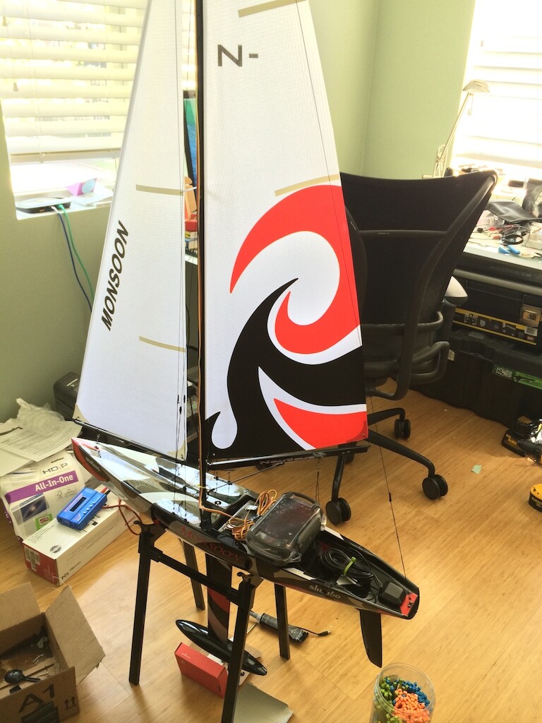
I'm using a $100 RC sailboat ("shunbo monsoon"). It came with a steering servo and a winch servo, and that's about it. I've hooked it up to a custom board that splices together a Sparkfun Arduino ProMini, an Invensense mpu9150 for the ahrs part, a Venus 638 gps chip and a simple MOSFET control circuit to only power the servos when they are in use. All of this is running off a 3-cell 11.1V 1500mAh LiPo battery.
The code and schematics are here:
Sunday was the first day out, and of course it was quite a disaster. A crappy hatch meant that when the boat heeled hard, it would take on water, which eventually sunk it. Luckily we had a fishing line tied to the backstay, so we rescued it. The brains were in an Otterbox dry box so they were fine, and surprisingly, the servos survived fine too (that said, i've bought waterproof replacements already)
When I got home, I realized that the axes of my compass were rotated by 90*, which explained why the boat kept wanting to go into the channel bank!
Anyway, wanted to get this out here, to share and get any feedback you guys may have. I expect to keep updating this as the project progresses. Here's a quick video of it in action:
The mosfets are n channels on the ground leg of the servos.
Blocking the current flow path on the ground lead may force voltage/current to flow back thru the servo control wire back thru the arduino to the common ground between the arduino and servo power supply. If the servo starts to heat up or behave erratically, this might be the reason. I haven't tried it, but a p-MOSFET on the servo power supply might be another choice.
Update:
I've continued working on this over the past year and a half, and have made some solid progress.
Hardware:
The original version posted here used an arduino micro soldered onto a daughter board that had the sensors + servo board. That didn't last long, as I ran out of code space, and inputs. I've moved to a fully-custom board by taking the Arduino Mega reference design, and adding my sensors and servos to it. I also stripped out the power management it had and replaced it with my own. It now has two SMPSs to provide a +6V rail for the servos and a +3.3V rail for everything else. It also gave me access to dedicated hardware serial ports for comms and GPS
Software:
A lot of tuning happened here. It still has a ways to go:
It can finally make it down a multi-waypoint track, but as you can see, it does get lost quite a bit. The main remaining issue is crossing the wind (tacking, or staying out of irons to use sailing terms). The wind was blowing from the west this day, and you can see long stalls any time the boat got close to pointing that way.
Debugging is difficult because the boat does need to be in water, and outdoors (because of the GPS), which becomes very weather dependent. I also don't typically bring programming equipment out because I don't want to open the waterproof electronics case while near water. That's probably the single biggest reason it's taken this long to make serious progress.
That said - it's still alive!
I'm keeping everything on Github, so feel free to look / use:
aren't standart servos 5V? if you are using 5V ones with 6v you should intigrate a 5V regulator (which is also in every arduino) ,otherwise it will might shorten the servo livetime
florian_markert:
aren't standart servos 5V? if you are using 5V ones with 6v you should intigrate a 5V regulator (which is also in every arduino) ,otherwise it will might shorten the servo livetime
The "normal" servo voltage range is 4.8V to 6V. It should be fine to run most servos with a 6V supply.
I had spent the summer tweaking the boat and the algorithms, until I was sure I was close to something better in August. Then, as I was making sure everything was working correctly, I turned the board on moments before taking the boat out to watch the circuit catch fire and release the magic blue smoke (see attachment). The post mortem showed that a stalled winch servo overloaded the 6V buck regulator and blew it up. So much for the rest of 2016.
I spent the remainder of the winter building a new circuit, a new boat (I had entombed the internals of the previous in polyurethane foam) and a new algorithm. The new circuit added the new InvenSense MPU 9250, an MPPT solar charger for the LiPo and some general cleanup (including a fuse on the 6V reg).
On the algo side, I ripped out the nonsense that was in there, and dropped in the lovely Arduino PID library for steering control. Maiden voyage this weekend went poorly I thought at first (the boat was zigzagging all over the place), until I realized that I was tuning P and I, but not D (don't ask). Unfortunately I realized that after I left the lake, so I'm hoping that next weekend will be the day it all just works!
Keep at it! I'm working on a similar project, using the Megatech Nirvana II as the basic platform.
So far, I've got the BNO055 IMU steering and GPS waypoint navigation working perfectly on a simple twin screw electrically powered model, and can set any powered course I like.
Next step is to come up with wind speed and direction indicators, so I've downloaded your Github material and will take a look at what you did.
Thanks! I've thought about wind speed, and really, I don't think it's necessary. On a real sail boat, your response to variable wind would be the tension on the backstay, the amount of sail area (through reefing) and potentially the jib sheet car positioning. None of those are available on an RC sailboat. Your only other option is to spill air from your sail by overtrimming, which you could do in response to just the heeling (roll angle) of the boat.
What refresh rate are you running at? I've noticed that the SD card is pretty slow, so writing to it too often slow down the whole thing.
I'm also thinking that a SOG indicator is in order. The GPS produces that, but it's not continuous enough to be able to play optimization games with sail position.. At that point, a wind speed indicator would become necessary, as you'd need to know whether a speed up/slow down was the result of a sail change or a wind change..