Understanding a circuit

Hello, I am very new to microcontrollers and just anything really to do with electricity. I am creating a program where I will be able to control 3 groups of LEDs using a transistor, resistors, and an Arduino.

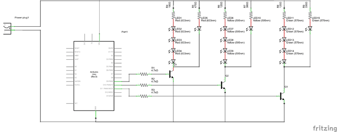
Does this diagram look correct? I am taking a 12VDC, 1.5 amp source and connecting both to the LEDs and the Arduino. Note the arduino is getting power from a plug.

Thanks.

You've got the wrong side of your 12v supply connected to the arduino GND. Otherwise, it looks OK.

There are a few problems with your circuit diagram mostly to do with symbols rather than the actual circuit.

The symbol you use for power is an AC signal/power source but you will be using DC. You connect it to ground on the Arduino when you will be connecting it to the raw voltage in via the power jack.

Then there is the 40mA on the outputs.

  1. Each output can drive a maximum of 40mA, but the chip has a maximum limit, of something like 120 to 200 mA so if the note on your diagram were correct you would be close already.

  2. A 1200 Ohm resistor connected between 5V and ground will pass approximately 4.1 mA so you are in fact more than OK here.

I am a bit concerned about the current and current limiting resistors on your LEDs though. I would aim for 20mA for a start and assume a switch on of 1.5V (It will be a bit higher though) and so I would expect above 470 for a single LED.

ChilliTronix:
There are a few problems with your circuit diagram mostly to do with symbols rather than the actual circuit.

The symbol you use for power is an AC signal/power source but you will be using DC. You connect it to ground on the Arduino when you will be connecting it to the raw voltage in via the power jack.

Then there is the 40mA on the outputs.

  1. Each output can drive a maximum of 40mA, but the chip has a maximum limit, of something like 120 to 200 mA so if the note on your diagram were correct you would be close already.

  2. A 1200 Ohm resistor connected between 5V and ground will pass approximately 4.1 mA so you are in fact more than OK here.

I am a bit concerned about the current and current limiting resistors on your LEDs though. I would aim for 20mA for a start and assume a switch on of 1.5V (It will be a bit higher though) and so I would expect above 470 for a single LED.

Yeah, couldn't find a DC symbol. Forgot to mention.

On #1, please explain more. Am I able to directly control output of the pins? I just figured the current was set to 40mA no matter what. How does it determine how much current to output?
Expanding on that, if I changed my current on the pin, would I need a new resistor between the transistor and the arduino pin?

Also, I used the LED data sheet to calculate the resistor sizes for the current/voltage going to the Leds. They are superbright LEDs and require more current.

Thanks

KenF:
You've got the wrong side of your 12v supply connected to the arduino GND. Otherwise, it looks OK.

So like this?

Negative just goes to Ground, and I do not connect it to the negative on the power supply?

You control the current on an output pin by controlling the resistance in the circuit. 40mA is just the maximum current you can draw out of the pin without bringing its output voltage below the valid high level threshold - try to draw more than 40mA and the output voltage will drop and you may damage the processor. It works the other way as well: you can sink 40mA into a low input pin, more than that could cause damage and will raise the output voltage above the valid low threshold.

Picture a direct short to ground: if you turn the pin high with zero resistance, you will get a lot of current and you will damage the processor chip. If you increase the resistance, the current will go down, until you eventually have no current flowing if the resistance gets infinitely high. It's just Ohm's law where the voltage is 5V (or 3.3 if that's what the processor is running on) and the current is what you want (up to 40 mA.) Given that voltage and desired current, you calculate the required resistance.

So if you want less current in the LED, use a bigger resistor - figure out the value by plugging the pin voltage, LED forward voltage, and desired current into your LED formula.

Your updated drawing is worse - you only have one side of the power supply connected so nothing will happen. I think the problem us that you are using a ground symbol in the upper left corner of the Arduino block, but I think you are considering that the supply connection.

Do some research on the standard schematic symbols - it's important to get them right. When you take a universally accepted symbol like the ground symbol, and use it for another purpose, it will just confuse everyone. (Including you, eventually!)

KenF:
Otherwise, it looks OK.

No it doesn't! :astonished:

You do not connect a single resistor to the bases of more than one transistor - you need a separate resistor for each.

HeyAwesomePeople:
So like this?

No!

Let's try to get this straight.

One circuit is that the negative of the power supply goes of the emitter of each transistor. The power supply positive goes to the LED strips. This involves the Arduino in no way - you do not make the ground connection through the Arduino.

Now, the ground connection on the Arduino does go to the power supply negative, but this is a separate lead - they only come together at the power supply negative terminal.

Similarly, you can run a wire from the power supply positive terminal to Vin on the Arduino or to the coaxial input jack. You could arguably make this jack the ground terminal to the power supply negative, but this is not advised as there is a risk of the plug being pulled out and current then taking alternate paths through the Arduino.

Current flows according to the resistance of the circuit. No (that is "open") circuit, no current flows. Any load connected to a circuit has a resistance of some sort which permits current to flow according to Ohm's Law. If the circuit resistance is too low (the worst being a direct connection or "short circuit"), then more current can flow than is safe and the voltage source - in this case the Arduino - will be damaged. 40 mA is the Absolute Maximum rating for the Arduino output - a figure that you must deliberately avoid reaching.

Without the LED data, I cannot comment further on whether your method of driving them is appropriate or not.

ShapeShifter:
You control the current on an output pin by controlling the resistance in the circuit. 40mA is just the maximum current you can draw out of the pin without bringing its output voltage below the valid high level threshold - try to draw more than 40mA and the output voltage will drop and you may damage the processor. It works the other way as well: you can sink 40mA into a low input pin, more than that could cause damage and will raise the output voltage above the valid low threshold.

Picture a direct short to ground: if you turn the pin high with zero resistance, you will get a lot of current and you will damage the processor chip. If you increase the resistance, the current will go down, until you eventually have no current flowing if the resistance gets infinitely high. It's just Ohm's law where the voltage is 5V (or 3.3 if that's what the processor is running on) and the current is what you want (up to 40 mA.) Given that voltage and desired current, you calculate the required resistance.

So if you want less current in the LED, use a bigger resistor - figure out the value by plugging the pin voltage, LED forward voltage, and desired current into your LED formula.

So to add resistance to the output pins, I basically need a resistor. In this case, I have a 5v version. So to keep in the required power limits, I would need at least a 125 Ohms resistor? This would draw 40mA and 5 volts. So my 1200 Ohm resistor between the transistor and pin should be good, yes?

The type of LED, Draw, and Voltage drop is listed on the diagram. It should match up and work well with the resistors in the diagram.

ShapeShifter:
Your updated drawing is worse - you only have one side of the power supply connected so nothing will happen. I think the problem us that you are using a ground symbol in the upper left corner of the Arduino block, but I think you are considering that the supply connection.

Do some research on the standard schematic symbols - it's important to get them right. When you take a universally accepted symbol like the ground symbol, and use it for another purpose, it will just confuse everyone. (Including you, eventually!)

Figured. Looked weird when I made it. What I am trying to do is split a 12Volt, 1.5Amp power source into two negative and two positives. One set of cords(a negative and a positive) goes to a connector to power the arduino, the other set goes to power the LEDs. I am not that great at diagrams, and am using DigiKey's Schemeit. It isn't the most clear/doesn't have all options I need.

I'll admit I am not the best at drawing diagrams. Very new to it.

Power supply is DC, splits into two. A positive and negative are fused to a plug in order to power the Arduino, and a positive line runs through the LED circuit, and back into the negative. With this in mind, does it look right?

Paul__B:
You do not connect a single resistor to the bases of more than one transistor - you need a separate resistor for each.

Meaning I would need 6 resistors to trigger 6 transistors? Why can't one line connect to two transistors?

Paul__B:
Let's try to get this straight.

One circuit is that the negative of the power supply goes of the emitter of each transistor. The power supply positive goes to the LED strips. This involves the Arduino in no way - you do not make the ground connection through the Arduino.

Now, the ground connection on the Arduino does go to the power supply negative, but this is a separate lead - they only come together at the power supply negative terminal.

Similarly, you can run a wire from the power supply positive terminal to Vin on the Arduino or to the coaxial input jack. You could arguably make this jack the ground terminal to the power supply negative, but this is not advised as there is a risk of the plug being pulled out and current then taking alternate paths through the Arduino.

Current flows according to the resistance of the circuit. No (that is "open") circuit, no current flows. Any load connected to a circuit has a resistance of some sort which permits current to flow according to Ohm's Law. If the circuit resistance is too low (the worst being a direct connection or "short circuit"), then more current can flow than is safe and the voltage source - in this case the Arduino - will be damaged. 40 mA is the Absolute Maximum rating for the Arduino output - a figure that you must deliberately avoid reaching.

Without the LED data, I cannot comment further on whether your method of driving them is appropriate or not.

Note: LED Data is within the diagram. Includes color, current, and drop

I think my horrible diagram is confusing you. The one line that goes from the positive to the Arduino is a positive and negative plug cord, just like the normal power supply that came with the Arduino uses.
I updated my diagram(see above) and made it two separate circuits, like it should be. The LEDs are a circuit and the Arduino is a circuit. The Arduino acts a a gate keeper for the current that goes through the LEDs by activating/releasing the transistor.

To me, with this in mind, all looks well. If you could, please point me to a better diagram system. This is my first project(little overkill, I know) and the parts have not gotten in yet, and thus I cannot take pictures of my setup.

You do not connect a single resistor to the bases of more than one transistor - you need a separate resistor for each.

The reason for this is no two transistors have exactly the same gain. When you share a base resistor, one
will drive more current than the other. You need to control the current individually.

Would it be unreasonable to ask why you don't just draw a schematic on a piece of paper and take a photo of it and post it ? That way you have total control of how the schematic looks.

raschemmel:
Would it be unreasonable to ask why you don't just draw a schematic on a piece of paper and take a photo of it and post it ? That way you have total control of how the schematic looks.

Oh gosh my drawing skills. Would take at least 3 times as long as doing on a computer. Even with a ruler...

raschemmel:
The reason for this is no two transistors have exactly the same gain. When you share a base resistor, one
will drive more current than the other. You need to control the current individually.

Okay, I will be sure to have one resistor per transistor.

HeyAwesomePeople:
Meaning I would need 6 resistors to trigger 6 transistors? Why can't one line connect to two transistors?

"Because!" 8)

Same reason you cannot use one resistor for LEDs in parallel - whichever exhibits the lowest voltage drop will take the lions share of the current, which is neither healthy nor effective.

HeyAwesomePeople:
Note: LED Data is within the diagram. Includes colour, current, and drop

Dare say I did not notice that. Was too alarmed looking at the circuit drawing. :astonished:

HeyAwesomePeople:
I think my horrible diagram is confusing you.

To say the least.

No, circuit diagrams do not work that way.

HeyAwesomePeople:
I updated my diagram(see above) and made it two separate circuits, like it should be. The LEDs are a circuit and the Arduino is a circuit. The Arduino acts a a gate keeper for the current that goes through the LEDs by activating/releasing the transistor.

It's still wrong! The ground to the Arduino is missing, and of course the need for separate resistors to the bases.

What ever tool you use to draw it- including a Biro- it's standard practice to have the 5V rail horizontal at the top, and GND along the bottom. The the (conventional) flow is downwards like water with gravity.

Attachment is a simple rotation of a screenshot of part of yours by 90 degrees.

Paul__B:
"Because!" 8)
No, circuit diagrams do not work that way.
It's still wrong! The ground to the Arduino is missing, and of course the need for separate resistors to the bases.

Haha I got a laugh out of reading that. What do you suggest for making a diagram? Paper and pencil? Some sort of program?

So basically, all that is wrong with my diagram, other than the separate resistors for the bases, is that you don't see a negative AND positive going to the Arduino?

How about we ignore that for a second and take a look at the rest. How does it look(excluding the extra resistors I need to put in to compensate for the transistors

JimboZA:
What ever tool you use to draw it- including a Biro- it's standard practice to have the 5V rail horizontal at the top, and GND along the bottom. The the (conventional) flow is downwards like water with gravity.

Attachment is a simple rotation of a screenshot of part of yours by 90 degrees.

I will keep that in mind.

HeyAwesomePeople:
What do you suggest for making a diagram? Paper and pencil? Some sort of program?

I recently started to use Express SCH- dead simple to learn and you can easily create custom components. The attached example (nothing to do with your project) took about 10 minutes to draw.

Paul__B:
"Because!" 8)

It's still wrong! The ground to the Arduino is missing, and of course the need for separate resistors to the bases.

Let's try this again, shall we? This time, I used positive at the top, negative at bottom.

Would this resistor setup work, or will it fail to draw the needed current?

That looks much better, and more closely follows the convention whereby the supply voltage is at the top, ground at the bottom and branches run vertically between them. It would be a trifle cleaner if the positive supply line did not go all the way along the top and come back.

You should clarify that the ground also goes to the Arduino and as I pointed out, to a GND terminal on it, not via the power jack. Finally, you could add the line from the positive supply rail to the Arduino, with similar symbol to those you have used for the +5V.

Most transistors you will use - such as a BC547 - have sufficient gain that to pass 20 mA to the collector, you need (much) less than 1 mA to the base, so a 4k7 resistor (4700) would work quite nicely. You certainly will have no trouble overloading the Arduino pins.

HeyAwesomePeople:
Oh gosh my drawing skills. Would take at least 3 times as long as doing on a computer. Even with a ruler...

I do sympathise, though I have no experience with programs other than (dare I mention it?) "Paint" and IrfanView. You are doing well with that software. My handwriting also is pitifully slow and illegible. Mind you, that is traditionally considered normal for my profession.

Paul__B:
You should clarify that the ground also goes to the Arduino and as I pointed out, to a GND terminal on it, not via the power jack.

Explain to me more that. Are you suggesting that the negative line(at the bottom) go to GND on the arduino?

Paul__B:
Finally, you could add the line from the positive supply rail to the Arduino, with similar symbol to those you have used for the +5V.

Most transistors you will use - such as a BC547 - have sufficient gain that to pass 20 mA to the collector, you need (much) less than 1 mA to the base, so a 4k7 resistor (4700) would work quite nicely. You certainly will have no trouble overloading the Arduino pins.
I do sympathise, though I have no experience with programs other than (dare I mention it?) "Paint" and IrfanView. You are doing well with that software. My handwriting also is pitifully slow and illegible. Mind you, that is traditionally considered normal for my profession.

Okay thanks!

Yes, it's perfectly acceptable to use paper and pencil, and take a picture of it to post it. Just like I've made a few edits to your diagram, and it was much faster to just print it, write on it, and take a photo, rather than try to edit it on the computer. (When I started learning electronics and drawing schematics, there were no computers and I did everything with pencil and paper -- OK, computers existed but they cost millions of dollars and took up whole rooms, nobody had one at home.) Please forgive the colors on the photo - I took the picture in front of window with a desk lamp on at the same time, and I guess my phone couldn't figure out the color balance with the simultaneous daylight and incandescent lighting.

The edits I made are simple: remove one of the horizontal supply rails and pull everything off of the one rail (makes it easier to read) and adding TWO supply wires to the Arduino (positive and ground.) You can't describe both signals with one line (even if the two conductors are in one cable.) The other edit I would do just to make it a little cleaner and follow convention is to move the bottom ground rail all the way to the bottom of the page, below the traces going between the Arduino and transistors.

We're getting to the point where it should work. But we can do some optimization. Let's look at the two red channels:

  • R1, L1, L2, L3, L4: 12V supply, 4 x 2.0V diode drops, and 180 ohms. That's 22 mA
  • R2, L5: 12V supply, 1 x 2.0V diode drop, and 470 ohms. That's 21 mA

Together, that's 43 mA, which is well within the current range of just about any transistor out there. There's no need for two transistors, it's just a waste of a transistor and resistor. So you can eliminate Q2, Q4, Q6, and R10, R9, and R8. Connect the signal that did go to the collector of the eliminated transistor, and hook it to the collector of its remaining mate.

While pencil and paper work just fine, there are several good free schematic editors out there. One that is becoming very popular with hobbyists is Fritzing: http://www.fritzing.org

Using Fritzing, I was able to throw together the attached in a few minutes (I would've still sketched it out on paper first.) This is only the second time I used Fritzing, so it took me a bit of a learning curve. One nice thing about Fritzing is that besides a schematic view, you can make pictorial and board layout views as well, all from the same initial drawing.

The general layout I followed is power at the top, ground at the bottom, with conventional current flowing down. The general flow of control signals is left to right.