I'm using a salvaged and repaired garage door opener to operate a homemade overhead bicycle hoist. I picked up a free "broken" garage door opener at the local makerspace, and after repairing one bad solder joint on the circuit board, it operates like a champ. There's just one problem: Those pesky safety beam sensors. Not only does my project not have a meaningful way to incorporate them, I simply don't have them as they were discarded before the opener was donated!
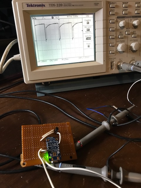
I tried the obvious approaches of shorting the terminals, leaving them open, and connecting a resistor or two, but it became obvious that the manufacturer wants to make it difficult to bypass the sensors for obvious liability reasons. I turned to the internet, and found this handy video that shows an oscilloscope being connected to a similar unit:

The video shows a Liftmaster garage door opener, which is the same company that manufactured the re-branded Craftsman garage door opener I'm working with.
The two connections have about 6 volts DC across them, with the middle screw (#2) being the ground/negative and the right screw (#3) being the positive. Shorting the two terminals together results in about 60 mA of current flowing, so there is a resistor in series that prevents a short circuit when the terminals are shorted together. Both the emitter and the receiver are powered by the voltage from these screws, and the output of the receiver is sent back to the head unit over these same power leads by shunting the leads together to create a pulse train. The oscilloscope work reveals the timing that signals the garage door opener that the beam is not obstructed. The absence of these pulses causes the opener to be unwilling to close the door, and it reverses to the open position automatically if the pulse train is lost while the door is closing.
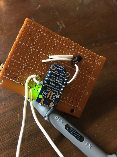
I used an ATTiny85, an N-type mosfet, a 7805 regulator, and a few caps & resistors to create a compact standalone unit that emulates the "all clear" signal and allows the opener to operate normally with broken/disconnected/missing sensors.
/*
garage door opener invisible beam receiver emulator
(use to bypass garage door opener optical beam sensor)

circuit:
 - 5vdc power provided to ATTiny via 7805 regulator across the ~6.4v supply provided by the opener's safety sensor terminals.
 - the usual capacitors connected to the 7805 are plenty to provide uninterrupted power to the ATTiny85 while the supply voltage is being shunted.
 - gate of mosfet or transistor connected to pin 2 of ATTiny
 - source of mosfet connected to ground of power supply and terminal 2 of Liftmaster/Craftsman opener
 - drain of mosfet connected to terminal 3 of Liftmaster/Craftsman opener
*/

int pin = 2;   // pin to which a transistor or mosfet gate is attached

void setup()
{
  pinMode(pin, OUTPUT);
}

void loop()
{
  // 6.5ms/.5ms code
  digitalWrite(pin, HIGH);  // shunt, then wait 0.5 milliseconds
  delayMicroseconds(500);
  digitalWrite(pin, LOW);   // open, then wait 6.5 milliseconds
  delay(6);
  delayMicroseconds(500);
}
It works like a champ! It worked on the first try while being powered by a battery, so I added the 7805 voltage regulator and allowed the microcontroller to be powered by the same voltage that it is shunting, and that also worked just fine on the first try.
According to the internet, lots of people tape the sender and receiver together and mount them on the ceiling by the opener to avoid installing them normally due to problems or personal preference. This is a way to do the same in a higher-tech manner, and also a cheap solution for a handy person if they are faced with a broken/damaged/malfunctioning sender or receiver and don't wish to pay big bucks to buy a replacement from the manufacturer.
Safety disclaimer: The safety sensors are intended to provide a measure of safety against accidentally pinning people or animals under the door while it is closing. By defeating them in any way, you are exposing yourself to some risk and need to make sure the door will be operated safely. If you have children or pets, you will want to think twice about having the sensors operating normally vs. not.