Can someone confirm if Arduino (basic or mega) can drive a monochrome OLED Display 256x32 pixels. the display we are looking at uses a SSD1326 display controller which i assume is quite a new device as i can't find any reference to it on these forums.
Which would be the best library to use for txt & images, i've been reading about the u8glib but i can not find any reference to SSD1326 controller so not sure if it will work.
This is a new project for me so i don't have any knowledge using OLED display's with Arduino but in the past i have built many RGB LED Strip projects with generic I/O / PWM .. etc
We intend to drive the display via 4 wire Software SPI but again any advice on if it would be better to use 3 wire (HW or SW) would be much appreciated.
The SSD1327 seems to have the same commands. Maybe U8GLIB_SSD1327_96X96_GR will at least show some pixels. If so, the U8GLIB_SSD1327_96X96_GR low level driver (u8g_dev_ssd1327_96x96_gr.c) can be modified to support this display.
If the SSD1326 is very compatible, then changing the macros from
Its encouraging to hear from you that it has a good chance of working and i will definitely give it a go over the next few days ... I'm still waiting on a 30PIN FPC breakout board to arrive from China but once that arrives it should be relatively easy to hook it up to the Arduino.
I'll let you know how i get on.
Question: How much memory does the U8Glib take up on an Arduino ?, at the moment we are using a Arduino Nano but depending on how things go with the display we have enough room to go up to a Arduino Mega if memory becomes an issue.
U8glib is optimized for minimal RAM usage. The actual amount of flash memory required for U8glib depends on the fonts and the number of glyphs inside the font. There is an overview page for the fonts, which also lists the size of the font in flash memory.
U8glib is optimized for minimal RAM usage. The actual amount of flash memory required for U8glib depends on the fonts and the number of glyphs inside the font. There is an overview page for the fonts, which also lists the size of the font in flash memory.
Oliver
Hi Oliver,
Many thanks again for your advice and support ...
Question: Does U8glib work with Teensy 3.1 ?
Our original project started off with using an Arduino Nano driving a strip of WS281x led's along with some basic I/O and a few SSR's to interface to the real world ....
As the project has developed we've added more features that are controlled via the Arduino, we've pretty low on spare overhead right now which is why we we're considering replacing the Nano with a ATMaga 2560 however as i'm sure you are aware the reference design of ATMega2560 is quite large which is going to be a problem for us.
We have big plans for the OLED if we can get it working with your U8glib and gain the results we are hoping for... We will be storing some full size (256x32) bit maps ... in light of this we are wondering if we should move up using a Teensy 3.1 MPC which does not have the headers fitted as standard and is around the same size and shape as a Arduino nano but with far more capability both in terms of built in memory and processing speed.
However we are keen to support Arduino as the project is aimed at that level of user ... my understanding is that Teensy 3.1 can be programmed/supported within the Arduino IDE using a plugin however having never tried it before i'm not sure how compatible it really is ....
What are your thoughts on using U8glib with Teensy 3.1 MPC ? am happy to give it a go you think it will work ?
olikraus:
To my knowledge some people had success with the Teensy. At least SW SPI should work.
Oliver,
4 wire Software SPI was always our preferred interface so that sound's promising ...
With regards to using U8glib on Teensy 3.1 do you know if it possible to do this with in the Arduino IDE using the Teensydruino plug-in ? (a set of make files i believe that support conversion of Arduino scripting commands to native ARM)
Many thanks for the update, we had confirmation from the display manufacture that the display driver is SSD1322 which i believe is fully supported by U8glib the distributer initially sent us the wrong application notes which is why we thought it was SSD1326
The device (RET025664A) we are using is 256x64 manufactured by RayStar
We have since decided to change the MCP from Arduino Nano to Teensy 3.1 which has HW SPI
According to this thread on the U8glib forum it should be possible to use HW SPI with U8glib using the COM module from here if we cant get that to work at initially at least we know we can fall back to SW SPI but my understanding is that HW SPI will give a faster FPS and be interrupt friendly.
Thanks for all your help and contributions to the community, will let you know how we get on
I just wanted to bump this thread because I'm having this exact same issue with the OP's original setup... 256x32 display, SSD1326 chipset, and SPI interface via U8glib.
I've confirmed the wiring several times, but the display is blank. I've tried two different displays, so unless both are bad ... it's not a hardware issue.
The pins are correctly configured, and if I swap in another display-type (SSD1306) with that same pin configuration and the SSD1306 constructor instead, that works fine with the program. So, some possible issues have already been eliminated but there is currently zero output or response from the 256x32 SSD1326 variant.
... So, it's one of the following issues, I think:
It won't run on 3.3V, but according to the datasheet it should?
The connector is bad or the datasheet is wrong for the SSD1326 display
There's some minor difference in SSD1326 vs. 1327 that's causing the entire thing to not work
There's some misconfiguration software wise here.
I'm kind of hoping it's the last one, because I can't find anything wrong hardware wise unless both displays are faulty. I copied the exact schematic from the datasheet and that matches another that I found floating online except two capacitors between the rails were polarized on this version and not on the other.
Any thoughts? Any help would be really appreciated! Thanks!
Hello.
i"m also trying to use the same display, it has very unique measurements, the driver IC SSD1326.
I'm trying to program with U8GLIB_SSD1327_96X96_2X_GR u8g(U8G_I2C_OPT_NONE).
You have suggested here http://forum.arduino.cc/index.php?topic=322725.0
to change #define WIDTH 256 #define HEIGHT 32
and #define U8G_16BIT 1
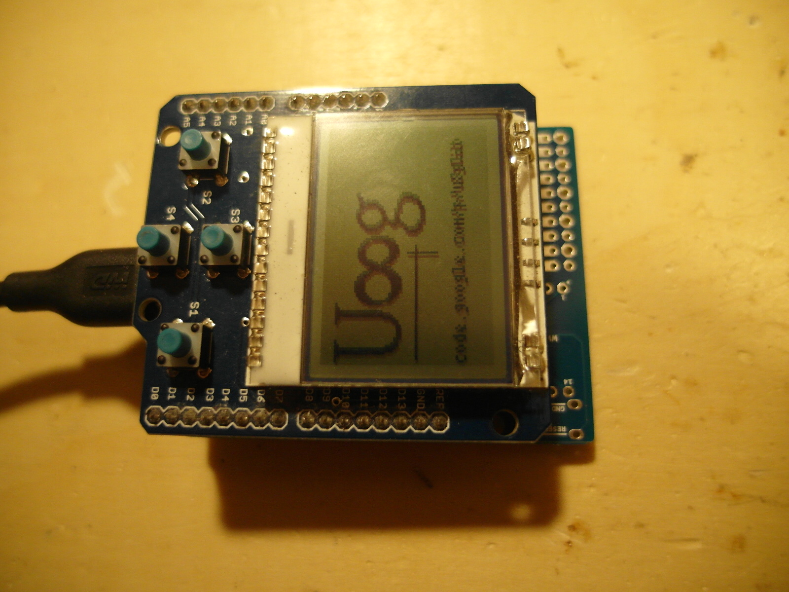
i'm getting this on the display, please see the attachment
I got this display from buydisplay.com , and they have some Demo Code, for this display.
I'm trying to transfer settings from that Code to u8g_dev_ssd1327_96x96_gr.c, NO LUKE.
Please help...
I guess the two controller require different memory/page setup. It might only require to change u8g_dev_ssd1327_2bit_prepare_page, but maybe more changes are required.
Without having such a device in my lab, it is difficult to say something.
I've recently acquired a couple of SSD1326 diplays.
The problem is that I'm not sure I'm doing the connections right (olikraus could you provide some pics of your connections to the arduino?) , because my knowledge of eletronics is pretty low.
I've also bought a controller board, and I've seen the screen working with the demo.
I've attached a couple pics of what I already have, and the code from the controller board (that I would like to avoid using).
Wow, very old thread. Meanwhile I have moved to u8g2. So please use u8g2.
Please also consider to create an issue on the u8g2 github project.
Connections I can not trace on your pictures, better attach a schematic first.
Did you use a 5V/3.3V level shifter? Your board looks like a classic Arduino Uno board (which usually is a 5V board). However I assume your display is a 3.3V board. So you might damage the display if you directly connect the display to your board.
i have a er-oled018-1 LCD after research you need to power the vcc pin with 12volt( with r1200 you have in the datasheet the schematics) because doenst have a pump up regulator like ssd1306