The above simulation is a best case. I used low value resistors, 1 K and 2 K, and low stray capacitance. The SD card has about 10 pf input capacitance so I only allowed 10 pf stray capacitance.
Still the signal does not meet the requirement of less than 10 ns rise time. Many new cards prefer 3ns rise time since they are designed for high speed, 50 MHz, max signals.
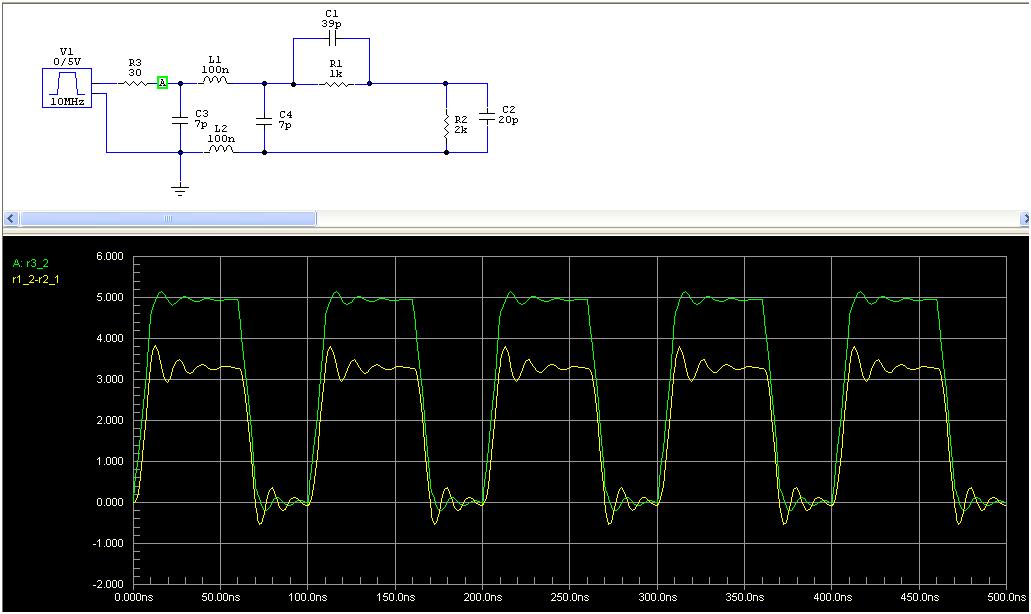
I did another simulation using values recommended by a number of users, 1.8K and 3.3K resistors. I also assumed a bit more stray capacitance, 30 pf total with 20 pf stray and 10 pf SD input capacitance.
The attached simulation result shows how bad resistor dividers can be. The blue trace is 5 V output from the Arduino and the black is what the SD card sees.
Be aware there are sdcard sockets with signals wired through a single resistor (mostly mounted on TFT lcd display modules). That is even worse than the signals wired via a voltage divider.
Added output "impedance" 30ohm @1.66mA, 10ns rising/falling edges (of the output signal) and 4in long flying wires (for example) with stray cap. Yea, the old freq compensation of the divider works
I am well aware of compensated attenuators. But it is not a good solution for this problem for a number of reasons.
You can't determine what the stray capacitance is so you can't pick a value for the cap. You can't even check that you have it right with a scope since the scope probe has a capacitance of 10 - 20 pf for typical scopes that hobbyists have.
You may not be able to easily get the value cap you need if you knew what you needed.
The input capacitance of SD cards vary. and the stray capacitance for any setup with jumper wires will vary.
Level shifters are required on three line, chip select, SCK, and MOSI. It's bad enough to use six resistors but now you need to add three caps.
I was waiting for the trimmer suggestion and you didn't disappoint.
How do you adjust the trimmers?
Back in 2008 I tried to look at this problem with a scope with a Tek 17 pf 1X/10X probe. It was hopeless. What I learned was don't buy the $120 switchable 1X/10X probe. Buy the fixed 10X low capacitance probe.
I was waiting for the trimmer suggestion and you didn't disappoint.
Frankly, the first thing which came to my mind was "3x varicap diode tuned by 3x 16bit DAC controlled by arduino such the sdcard works reliably..", but then I changed my mind..
Back in 2008 I tried to look at this problem with a scope with a Tek 17 pf 1X/10X probe. It was hopeless.
I would use 1k resistor (the tip) wired at the open end of a 50ohm coax of 1m length - (and a very short gnd wire from shielding), the other side of the coax terminated by 50ohm at oscope's input. That gives you ~20x attenuation, but GHz bandwidth.. No messing with probe's compensation required..
would use 1k resistor (the tip) wired at the open end of a 50ohm coax of 1m length - (and a very short gnd wire from shielding), the other side of the coax terminated by 50ohm at oscope's input. That gives you ~20x attenuation, but GHz bandwidth.. No messing with probe's compensation required..
This won't work with these voltage dividers. This will have ugly results on the scope.
Use 2k resistor as the probe's tip in the above setup (you get 40x attenuation), and the probe itself will work as the R2 in my schematics (called R1 in your first schematics at the top of this topic - we are talking the 2k one at the sdcard's input to gnd) in the sdcard's voltage divider (that is its double role - as the probe signal input as well as the R2 in the sdcard's voltage divider as the input impedance of the probe will be 2050 ohm).
The tip resistor's wires shall be 2-4mm long, the gnd wire from the shielding 10-15mm.
That must work and you will see "pitoseconds" details provided your DSOX96204Q Infiniium is switched on
PS: with DSOX96204Q Infiniium you can observe all 3 signals at once, and I am sure the oscope has got a serial output thus arduino may judge whether the sdcard's signals are good enough to proceed with "sd.begin()" or not
The voltage divider can't drive a scope that has a 50 ohm input. That's what the DSOX96204Q uses for high GHz bandwidth.
Read the above article about low impedance high bandwidth scopes.
You could use an active probe but even these have a few pf for reasonable cost, not $4000.
Edit: You are just trying to invent a passive probe. You can't just put a resistor before the coax. You won't be driving it with a 50 ohm source so the signal will be distorted. You need a cap in parallel with your resistor to compensate. This is just a passive probe for a 50 ohm input scope. Your probe will have a very low impedance, in the kohms.
My scope has a 1 M input so my 10X passive probe has a 9 M resistor and about 12 pf of capacitance.
@fat16lib: See the schematics with your measurement setup below. It will work. You do not need $xxxx probe for it. Just try it..
Simply solder the 2k resistor at the central wire of the coax (you must not cut your o'scope probe, do use a freshly cut 100cm long piece of 50ohm coax instead ). Use as short as possible lengths of the resistor's and gnd's wires at the probe side.
Mount an 50ohm BNC connector at the other side of the coax, and,
You will get quality probe (~1GHz BW) for high speed measurements (high speed, large BW measurements are always made low impedance).
Mind you have to switch your o'scope to 10mV/div (or something like that) in order to see the sdcard's 3.3V input signal full screen (because of aprox. 40x attenuation of the probe setup ).
Also, do not forget 50ohm BNC terminator at the o'scope connector (or, when available with your o'scope, switch o'scope's input to 50ohm impedance). It will not work when your o'scope input impedance will stay unterminated (unterminated means 1M||20pF input impedance - the standard setup). It must be terminated 50ohm hard (AC/DC path).
Try and see..
Note:
The C2 below is the stray capacitance of the sdcard's socket and sdcard's chip input as estimated by you.
The C1 is an experimental divider's compensation as suggested above.
C1 and C2 is not related to the "probe" setup itself.
The "probe" below does not require freq compensation within a reasonable BW range (<1GHz).
The "parallel parasitic capacitance" of a junk box 0.25W small sized "probe tip resistor" is estimated <0.5pF..
Tried it - doesn't work. The coax has a lot of capacitance so the signal is distorted just like the distortion from the divider that this article is about. You are just building the same uncompensated attenuator the article is about.
I didn't need to really try it, I just did it to humor you. I had two years of electricity and magnetism getting my PhD.
This has nothing to do with the problem:
The "parallel parasitic capacitance" of a junk box 0.25W small sized "probe tip resistor" is estimated <0.5pF..
You must work with signal sources that have very low impedance Then you can use a resistor as an uncompensated probe.
At 8 MHz the coax is not a transmission line, just a cap at
Capacitance (pF/ft)
30.8
RG-58/U
I could just use a standard 100X probe and get as good or better. At $74 100X probe has 3.5 pf.
You can't even use your setup on SD modules that have small surface mount resistors. You would need to unsolder resistors on other boards. How do I know the stray capacitance will be the same?
The coax has a lot of capacitance so the signal is distorted just like the distortion from the divider that this article is about.
The capacitance of the coax has nothing to do with the signal distortion. We use x-kilometers of coaxes without distorting any signal traveling inside..
You must work with signal sources that have very low impedance Then you can use a resistor as an uncompensated probe.
Is 1k a large impedance?? Mind the input of the coax at the bottom of R2 sees 50ohm.
At 8 MHz the coax is not a transmission line, just a cap at
A coax does represent a transmission line at any frequency..
We may discuss velocity factors, attenuation at specific frequencies, impedance matching of a transmission line I/O.. But capacity of a coax in pF/m is related to the attenuation of the traveling signal only.
You want to see the shape of the signal, you do not care much on dB/m (it means how big the picture on your screen will be) as you have a switch there called V/div so you may increase the picture if you want, am I correct?
RG-58 is a great coax for your purposes, trust me..
a coax in pF/m is related to the attenuation of the traveling signal only
A meter of coax is about a 100 pf cap at low frequency.
Time for you to go to school and learn how a passive probe works.
If the scope internal resistance RS = 1 M?, its capacitance is CS = 25 pF and the cable connecting the probe to the scope has capacitance CC = 150 pF, find the values of the required probe resistance RP and capacitance CP for 10:1 attenuation. Make sure that the same attenuation is also valid for dc measurements.
Hint: Consider independently two voltage dividers, one resistive the other capacitive. Note that they are connected in parallel and should give the same attenuation.
As you have admitted you were not successful with measuring the shape of the signal at the R1/R2 divider in 2008 I must admit I am not successful with selling the key point here today :).
A simplified approach, assuming the ideal world neglecting a lot of factors maybe:
the capacitance of the coax and the shape of the signal:
When you take a coax_A with 10pF/m and coax_B with 10000pF/m, both of length 1000m, both with a characteristic impedance of 50ohm (50 ohm coax) and you terminate the very far ends of both coaxes with 50ohm terminations you will:
a. when starring into the near end of the coax_A or B you will see 50ohm
b. when you feed the near ends of A or B with a 100MHz signal (amplitude 5V) out of signal generators with 50ohm output impedance (pure resistive one) you will see the same signal at both far ends (the shape of the signal will be the same at A and B ends).
What will not be the same (because of different pF/m) will be the amplitude of the observed signal, the A signal will have (for example) 1V amplitude, the signal B (for example) will have 1uV amplitude. But the shape of both will be the same.
c. when you feed the near ends of A or B with a 100MHz signal (amplitude 5V) out of signal generators with 5000ohm output impedance (pure resistive one) you will see the same signal at both far ends (the shape of the signal will be the same at A and B ends).
What will not be the same (because of different pF/m) will be the amplitude of the observed signal, the A signal will have (for example) 0.01V amplitude, the signal B (for example) will have 0.01uV amplitude. But the shape will be the same.
Now the divider (from my schematics):
a. the signal source for the probe is the input of the sdcard, call it S point
b. the impedance at S is unknown
c. we cannot measure at the S point because it will distort the measurement (you saw it in 2008), unless you posses a $xxxx active probe
d. so we try to measure only a small fraction of it, at 50ohm impedance as seen at the coax input (because the 50 ohm coax is terminated by 50 ohm termination), moreover the measurement is done at the "cold end near the GND" so we love it
e. the R2/50ohm input coax impedance creates roughly a 1:40 divider (2000ohm/50ohm), and because the R2 is purely resistive it will work without distortion of the signal, it just decreases signal amplitude (40x)
f. the 100cm RG58 coax, because of its 39pF/m will decrease the amplitude of the signal even more, let say 1.3x (for example)
g. the signal at the far end of the coax, terminated by the 50ohm BNC termination will have the same shape as the signal at the point S - that is an important point we must agree somehow.. The few pF stray capacitancies at the coax ends will not have a big influence here as they act at 50ohm impedance, so the signal will be "distorted" maybe somewhere at very high frequencies. Let us assume we can tolerate that somehow.
h. the amplitude of the signal at the 50ohm BNC termination (50ohm resistive) will be then aprox 40*1.3 smaller (for example) than at the point S - that is not a problem here as we may amplify it later on. Important for your experiment is the shape of the signal will be "the same" as the signal at the point S, but with much lower amplitude.
i. the "probe itself" (from S via the coax to termination impedance) has of course a certain bandwidth. So its frequency characteristic decreases somehow with frequency. The BW of that probe, with 1k probe tip resistor has been elaborated many times so you may find the AC characteristic at several sites. Worked well till 1GHz. That means the declining of the spectral components above few hundred MHz inside the signal will "distort" its shape somehow, but much less than you may get with $xx probes, even compensated.
j. moreover, in the DUT setup luckily, the R2 (the lower part of the sdcard's divider as well as the probe's tip) is the part of the DUT - it makes the stuff easier to setup.
Oscopes experts may add what happens when you connect the properly terminated coax to an modern oscope. You may probably set the amplification in the way it compensate for the external dividers (such you see the true amplitude as seen at the point S), as well for frequency characteristic of the oscope itself.
Important for your experiment is the shape of the signal will be "the same" as the signal at the point S, but with much lower amplitude.
This is not true. We are not dealing with a transmission line. This is a totally different problem.
We are dealing with a divider where one impedance is a 2 k resistor and the second is a 50 ohm resistor in parallel with about 150 pf of cable and scope capacitance.
The signal at the scope is not an attenuated version of the SD input.
You just failed the scope probe lab above.
By the way, the capacitive loading by a passive scope probe has nothing to do with the scope input resistance. Look at the probe circuit.
The probe capacitance is:
Cp = (Cc + Cs)/(X-1)
Where Cc is the cable capacitance, Cs is the scope input capacitance and X is the attenuation factor. This is the the value of Cp required for frequency independent attenuation of X.
After the 2008 experience I bought a fixed 100X passive probe and it has a very small loading capacitance. In principle it should be about 2 pf but I think it is more like 3.5 pf because of extra stray capacitance.
Your way is better than my original 1X/10X probe that had almost 20 pf but not as good as my 100X probe. You just are making a poor quality 40X probe.
I couldn't use you method in 2008 since I was measuring a signal on a shield. I couldn't probe the GND end of the resistor. Guess your way wouldn't have helped.
Edit: I got a better result with your method by not using any coax. I just put a 50 ohm feed through terminator in the scope and connected that to a BNC with short pigtails. I put the Arduino with the resistor divider right next to the scope. The rise time then looks like I expect. This eliminates the cable capacitance and only leaves the 20 pf scope divided by 40 or almost nothing.