Building an Arduino Controlled CNC

Disclaimer: I am a beginner, myself, with Arduino, CNC's, and power tools.

So there have been a lot of posts already about building CNC machines in which the stepper motors are controlled by an Arduino. I know this because I've spent the past 3 days reading and trying to understand them. What I'm going to try to do here is consolidate what I think I've learned in a way that a beginner can understand. I will also ask the questions that I feel are left unanswered for beginners like me. My ultimate goal is to build the cheapest possible desktop CNC machine with the least amount of tools and skill. Things I'm clueless about will be highlighted in red and will hopefully be answered in the responses to this thread.

Part I

Step 1: Build a CNC Stage

This what will translate your material in 2-3 dimensions and press it against the cutting tool. There are tons and tons and tons of guides/instructions/kits out there to build your own cnc stage. Here are some resources:
http://buildyourcnc.com/default.aspx

...(there are tons of websites out there if you AltaVista them)

But lets assume that you can't cut paper straight and the only tools in your house are the hex keys from your Ikea purchases. Not to worry, there plenty of kits that come with all the parts already cut and ready for you to assemble. The absolutely cheapest that I could find was the kit from Zen Toolworks ($350 with shipping), but it is also the smallest having a range of 7x7x2in. It comes with the stepper motors you need to drive stage, which are actually fairly powerful for the size of the stage. Here are some options for ready to assemble stages:
http://www.zentoolworks.com/
http://www.zenbotcnc.com (not the same cnc or company)
lumenlab.com - lumenlab Resources and Information.
....(the more you pay, the more you eat)

I went with the Zen Toolworks Small CNC because of the cost and my needs. It makes no difference to the arduino which stage you pick so long as we tell it the movement characteristics.

If someone knows of a cheaper option that requires no cutting/drilling, please post a reply.

Step 2: Stepper Motor Driving

Stepper motors are not like DC motors where you can just hook up a power line and they'll spin. They work with a series of coils that must be driven on and off in the correct order to step the motor forward or backwards. In order to drive the motors, we will need a ...wait for it...stepper motor driver. The driver takes signals from your Arduino and converts them to steps for your motors. Since you have three stepper motors (one for each axis) you need three stepper motor drivers.

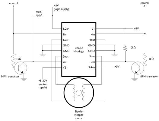
When I first started looking for drivers I was tempted to buy the EasyDriver from Sparkfun, but then I read about how they are typically under powered for most CNC projects. The motors from the Zen Toolworks kit require a maximum of 1.3A. I found this thread started by aventgps where he describes his own machine and on page two his stepper motor drivers using a L293D:
http://www.arduino.cc/cgi-bin/yabb2/YaBB.pl?num=1258354000/15
I found a similar design here using a L293A or SN754410:
http://www.contesti.eu/opensource/xyz-dc-motor-controller
More info here:
http://www.tigoe.net/pcomp/code/circuits/motors/stepper-motors

This second project seems very promising as a one stop shop for your Arduino CNC needs, except for the fact that all of the arduino code is offline. Also notice the temperature sensor and fan control. I'll talk about why this project won't need such things further down.

In the end I decided to go with the beefier but similarly priced L298N which can handle 2A (which would be good if I ever decide to upgrade my system). You could also stack two of the SN754410 on top of one another, but you will have to wary of thermal management. These chips all have the same interface, so wire them according the to provided diagram.

http://www.newark.com/texas-instruments/sn754410ne/ic-motor-driver-half-h-1a-dip-16/dp/08F8145

aventgps diagram shows how to connect the 4 wire stepper motor and the contesti.eu page covers how to connect a 6 wire stepper motor. The Zen Toolworks motors are Nema 17, 2 Phase, 4 wire.

Note: You will see stepper motors referred to as Nema 17 or Nema 23. This does not tell you what internal configuration your motor has. This is the chassis design and size. So a CNC stage that takes Nema 17 motors, physically has the mount for that size stepper motor, but not all Nema 17 will provide the same power or will be 4 wire, 6 wire,8 wire...etc.

Step 3: Power Supplies

You will need at least two power supplies.

  • One power supply will be 5V and will power your Arduino and stepper motor drivers.
  • The second power supply will also be hooked up to the motor drivers, but this will be the power that is delivered to the motors to physically move them.

To be honest, this is where the knowledge out there runs thin for me. The motor driver (L298N) can take any where from 4.5 to 46V (check the datasheet of your driver).

I figured out how to size your power supply:

The coil resistance determines the maximum current: Imax=Vmax/R. You want Imax to be less than what your driver and motor can handle and not overheat. The maximum speed of a stepper motor is limited by its inductance: dI/dtmax=Vmax2/L. The rate of change of current is L X R. Anything above Vmax2 is a waste.

Vmax = Imax*R
Vmax2 = L2R (L is in mH)
Vmin = I
R

Vmin < V < Vmax || Vmax2

So pick a power supply that can provide the desired current you want flowing though your motor, "I", at a voltage, "V", between Vmin and Vmax or Vmax2, whichever is lower. Imax is determined by the maximum either your motor or driver can handle, whichever is lower. V must also be between the max and min your driver can handle.

Step 4: Limit Switches

Your system, for the most part, runs blind. It steps the motors without any regard for the actual position of the cutter head. So if you were to start your system with the cutter head 1 inch away from the edge of your stage limit, and you told the system to move 3 inches in that same direction, the system would reach the end and keep stepping away, potentially damaging your stage. To solve this problem, we place limit switches at the extreme ends of the range of the stage. When the stage runs into these switches and triggers them, it tells the code to stop moving in that direction (or to quit all together). You can buy limit switches anywhere, or you can make your own using metal plates, screws, and wire. When the screw on the stage touches the metal plate on a fixed point, it completes a circuit and acts the same as any store bought switch. You'll need 6 switches at a minimum (2 for each axis).

When we wire these switches to the Arduino, we have three options as to how we do it:

  1. Each switch gets its own pin on the Arduino (digital or analog).
  • This will take up the most number of pins.
  • The benefit will be that the you will know exactly which axis has reached its limit and in which direction.
  1. All switches are connected to a single pin directly (digital or analog).
  • This takes the least amount of pins and work.
  • You will not know which limit switch was triggered but you do know the stage must stop whatever it was just doing.
  1. All switches are connected to a single analog pin using voltage dividers.
  • Takes up no digital pins.
  • You know which switch was triggered.

Option 3 seems like a no brainier to me. The layout would go something like this:

5V----5k ohm---analog pin ---SW1---1k ohm---SW2---1k ohm---....---1k ohm --- SW6

Step 5: Cutting Tool

This is what you will mount to your stage to cut your material. This is very open depending on your needs. Zen Toolworks sells their own mount and motor:
http://www.amazon.com/Spindle-Zen-Toolworks-Machine-Holders/dp/B0039HCK6S

But you can use any dremel or power tool you can mount on there. However you mount it, make sure it is sturdy and does not move. People have used zip ties.

Step 6: Arduino

Buy one and learn how to program it. If you used Option 3 on the limit switches, you'll have plenty of I/O lines with any of the ATmega328 options.

Step 7: Extra Bits

You are going to want 1-3 relays so that the Arduino will be able to toggle the power on and off for the stepper motors. You'll want 1-3 transistors so that the Arduino doesn't power the relays itself. Follow this if needed:
http://tronixstuff.wordpress.com/2010/04/20/getting-started-with-arduino-chapter-three/
You'll want relays that can be triggered with the 5v available instead of 12v.

Get some perfboard for soldering everything, or just soldering everything into a ball. So long at the the stepper drivers get sufficient cooling, it makes no difference.

That is it as far as hardware goes.

Disclaimer: I am a beginner, myself, with Arduino, CNC's, and power tools.

To recap:
3D Stage with three stepper motors - $350
Stepper motor drivers - $10-$20
5V Power supply for the Arduino and drivers - $5
4.5V-46V? power supply for Stepper motors - $10-$20
Six limit switches - $1-$5
Cutting Tool - $20-$25 (or more if you want)
Arduino - $20
Extra bits -$5-$10

Even with the the $350 Zen Toolworks stage, the entire parts list should not cost more than $450 total.

You can add other bells and whistles like fan controls and temperature sensors, but this seems really dumb to me. This is a CNC machine. It will be loud. It will consume lots of power. If you need a fan for cooling, wire it to be always on with the stepper motors. A temperature sensor might be handy for shutting off your system if it is overheating even with the fan on, but that just mean you didn't design your system well.

Part II

Step 1: Arduino Code

Every single guide for making an Arduino controlled CNC usually stops at Part I and then tells you to follow what they do at RepRap. Well, that leaves most beginners with few options but to now start learning about the RepRap and the mess that is going on their wiki pages. I'm sure that is educational and helpful in some ways, but if you just want to start using your CNC, this feel like a kick to the groin. I'll hopefully streamline the process.

What you want a CNC machine to do, is to read a computer file that describes your part, figure out what motions by your CNC machine will carve your part out of your material, and then to feed the motions to the stepper driver in the correct order and pace. The bad news is that your Arduino would struggle with a majority of those tasks. The good news is that your computer can do the most of what is needed and just tell the Arduino to take care of the low level signals to be sent to the driver. The Arduino will also monitor the progress and stop if the limit switches are hit or you tell it to stop through the serial port.

So we are going to setup the Arduino with code that will have it listen to the serial port, record the movements it needs to make, parse them into stepper motor commands, and then execute them. To do this we will use something called G-Code. Straight from RepRap wiki:
"G-Code is a commonly use language to control CNC machines. G-Code is a light-weight, simple to parse format, designed to be able to run on modest hardware...Several software packages can generate G-Code, so using this firmware allows you a degree of flexibility."

The Arduino G-Code interpreter from RepRap is what we are looking for:
http://reprap.org/wiki/Arduino_GCode_Interpreter

aventgps, used this code for his build. He modified it to for his needs (removed the extruder code, made it work with his stepper motor driver). His code can be found here:

Main post here:
http://www.arduino.cc/cgi-bin/yabb2/YaBB.pl?num=1258354000/0

You will need to adjust the firmware for your platform. The first thing you will need to do is edit _init.pde (they all open at once in the Arduino IDE, click the tab to edit _init). Follow the directions at the RepRap page for adjusting most of the parameters:
http://reprap.org/wiki/Arduino_GCode_Interpreter

At the bottom of the _init.pde file you will find your pin assignments:
#define X_STEP_PIN 8
#define X_DIR_PIN 9
#define X_MIN_PIN 4
#define X_MAX_PIN 2
#define X_ENABLE_PIN 15

The first two are the pins connected to the X axis driver as control 1 & 2:

The orientation does not matter (as far as I can tell). I think swapping the pins will cause the stepper motor to run in reverse.

The next two are the limit switches for the X axis. This is setup for Option 1 in the description I gave in Part I.

To set this up for Option 2, I think you just change the max and min to the same pin. Can someone confirm?
To set this up for Option 3, you will need to change the code a bit in stepper_control.pde to match your voltage divider setup. If anyone has already done this, please post it here.

(I have not actually gotten to this point in my own build. But I am laying it out as I understand it. If I do adjust my code for Option 3, I will post it here.)

Lastly, X_ENABLE_PIN is the pin that will enable and disable the power to the X axis stepper motor. This will be connected to the relay discussed earlier in "Extra Bits". This is important because you don't want your stepper motors powered all the time. That would cause thermal problems and would make your stage unmovable even when you weren't running code. You could provide a relay for each of your motors separately, or just use one so long as it could handle the power. Using only one pin from the Arduino to control the relay(s) is a smart idea unless you plan on doing something fancy.

Continue to adjust the parameters for the Y and Z axis.

Upload your code to your Arduino, and you will be set hardware wise.

Step 2: Computer Software

Now that the Arduino is ready to receive G-Code commands, you need software on you computer to send them to the Arduino over the USB cable. I really have not researched this that well. ReplicatorG was recommended by the ReRap Wiki:
http://replicat.org/download

It runs on the three major operating systems. Once you download it, you will need to edit machines.xml to add your own CNC machine parameters. You can adjust the parameters of the CNC cupcake to that of yours. Here is a detailed guide to editing machines.xml:
http://replicat.org/machine-configuration

Again, I'm not at this point in my build yet, but I assume you need to adjust :
http://replicat.org/geometry
and . Set the driver to serialpassthrough:
http://replicat.org/serialpassthrough-driver

Once you have this setup, you'll be able to directly send commands to your stepper motors from your computer. Use this as a guide to the commands at your disposal:
http://reprap.org/wiki/Mendel_User_Manual:_RepRapGCodes

(Not all the commands will work with our setup.)

Step 2.5: Generating G-code

Everything in this section I am assuming will work.

You want to now create 3D objects that can be interrupted into G-code to be sent to your Arduino. You have lots of options for generating your 3D objects. Here is a free option:
http://sketchup.google.com/

Here are tutorials for using it:
http://sketchup.google.com/3dwarehouse/cldetails?mid=36e1fa0d054a15eecc725c514c21d975&prevstart=0&nfpr=1&hl=de&ct=lc

Once you have your sketchup file ready, you can follow this tutorial to convert it to STL format:

Once you have it in STL format, the ReplicatorG program can convert it to G-code and send it to your Arduino. Follow this guide:
http://replicat.org/usage

And there you have it (hopefully). I'll post when I have my machine up and running. I bought my first Arduino a few weeks ago, so this has been a HUGE project for me. Thank you to everyone who has supported this community. Props to aventgps, contesti.eu, cerebralmeltdown.com, Zach Smith, RepRap, and the Arduino community.

If there is anything incorrect that I posted, please correct me. If there is anything I left out, please post it.

WHAT "X axis driver"? Please don't make us slog through your epic postings and guess what you are asking about. Cite the specific URL to the technical details.

Off the top of my head, it seems extraordinarily unlikely that you can just swap any two pins unless you swap everything to match. And I would need a really, really good reason to do that, to avoid messing up future documentation and references. I can't think of any good reason right now.

The X axis stepper motor driver:
#define X_STEP_PIN 8
#define X_DIR_PIN 9

We are clueless unless you tell us what explicitly what you are asking about.

From Part I, Step 4 Limit Switches:
Option 1: Connect all 6 limit switches to their own input on the Arduino
Option 2: All switches are connected to a single pin directly
Option 3: All switches are connected to a single analog pin using voltage dividers.

Sorry for the confusion.

For the stepper motor power supply, you are saying that I should be looking in the stepper motor datasheet for a specific voltage to run it at?

Calculating the voltage for the stepper is apparently not as easy as using the ratings on the motors.... for reasons I don't understand.

I duid however remember running across this snippet in a thread on www.cnczone.com (Which is a superb resource for all things CNC and just general machining type things...) Below is the snippet, from this thread: New Machine Build How crazy is this idea for an X2 "staged" CNC conversion?


Thanks for the info guys.

Hoss (or others), how do you determine the volts for a stepper? I looked at the datasheet linked to and see the 3.5A rating but the rated voltage is 2.55.

Cheers,
Michael


Michael: We've been using this equation to determine motor drive voltage:
32 * square root(motor inductance in millihenries, mH)

For the KL23H2100-35-4B it's 32 * (2.8)^0.5 = 53.546, or 54 Volts.
(For the non-math nerds, square root is the same as raising a number to the 0.5 power).

tom

That pin definition does NOT appear to be compatible with the motor controller you cited.
My guess is that it would not work no matter which way you connect it.

The stepper motor driver is directly from the references of the Stepper Library:

I'm just trying to figure out how it was implemented in the referenced RepRap code as the person that cited the code said he used the code with this driver

do_step(X_STEP_PIN, X_DIR_PIN, x_direction);
...

void do_step(byte pinA, byte pinB, byte dir)
{
        switch (dir << 2 | digitalRead(pinA) << 1 | digitalRead(pinB)) {
            case 0: /* 0 00 -> 10 */
            case 5: /* 1 01 -> 11 */
                digitalWrite(pinA, HIGH);
                break;
            case 1: /* 0 01 -> 00 */
            case 7: /* 1 11 -> 10 */
                digitalWrite(pinB, LOW);
                break;
            case 2: /* 0 10 -> 11 */
            case 4: /* 1 00 -> 01 */   
                digitalWrite(pinB, HIGH);
                break;
            case 3: /* 0 11 -> 01 */
            case 6: /* 1 10 -> 00 */
                digitalWrite(pinA, LOW);
                break;
        }
      delayMicroseconds(5);
}

Using the stepper library it seems like it would be:

Stepper(steps, pin1, pin2)
...
step(steps_to_move)

Looking inside stepper.cpp;

    switch (thisStep) {
      case 0: /* 01 */
      digitalWrite(motor_pin_1, LOW);
      digitalWrite(motor_pin_2, HIGH);
      break;
      case 1: /* 11 */
      digitalWrite(motor_pin_1, HIGH);
      digitalWrite(motor_pin_2, HIGH);
      break;
      case 2: /* 10 */
      digitalWrite(motor_pin_1, HIGH);
      digitalWrite(motor_pin_2, LOW);
      break;
      case 3: /* 00 */
      digitalWrite(motor_pin_1, LOW);
      digitalWrite(motor_pin_2, LOW);
      break;

It looks as though the code is the same. Or am i missing something?

You have provided NO reference to what you are asking about. I am unable to even understand the question, much less attempt an answer.

A limit switch on a CNC platform works by notifying the controller that the platform has reached the end of the platform's range. The options provided are different configuration you can connect the six limit switches required for any 3 axis CNC machine to the Arduino. All I am asking is if the RepRap code is configured in a way that instead of providing a separate input pin for each limit switch, I can connect them all to the same Arduino pin.

I am suggesting that you may be wasting your $$$ buying anything (including motors) if they don't provide even the basic details. If a seller is too lazy to provide even the essential specifications, then I will move on to a more intelligent source. Life is too short to deal with fools.

Thank you for your insight on choosing a power supply for stepper motors.

Hint: Quiting paragraphs and paragraphs of text and expecting us to slog through it is probably asking more than you can reasonably expect from people here. Also specific context is needed to answer detailed questions.

Well this wasn't meant for you to slog through. I was trying to help beginners like myself who have no experience and have no idea where to start. I was hoping others who have built Arduino controlled CNC machines could fill in the parts that I couldn't find in other posts.

Michael: We've been using this equation to determine motor drive voltage:
32 * square root(motor inductance in millihenries, mH)

For the KL23H2100-35-4B it's 32 * (2.8)^0.5 = 53.546, or 54 Volts.
(For the non-math nerds, square root is the same as raising a number to the 0.5 power).

tom

Thank you for that Troy. I just wish there was some explanation as to how that equation was formed.

More importantly, what is wiggle room on the voltage? If that is the optimal voltage, how far off do you have to be before it becomes unacceptable?

The optimum voltage is as much as you can get away with without over currenting the motor. The higher the voltage the quicker you can get the current into the motor coils and the quicker it will turn.
You need a chopper stabilised current driver to make sure you don't over drive things.