I have been happily using HC-05s and HC-06s as slave devices is many different projects. I have now started to play experiment with the HC-05 as a master device. I have no issue getting in to AT mode but I have found that some commands only seem to work when pin 34 is HIGH. This does not seem to be standard. Does anybody else have modules like this?
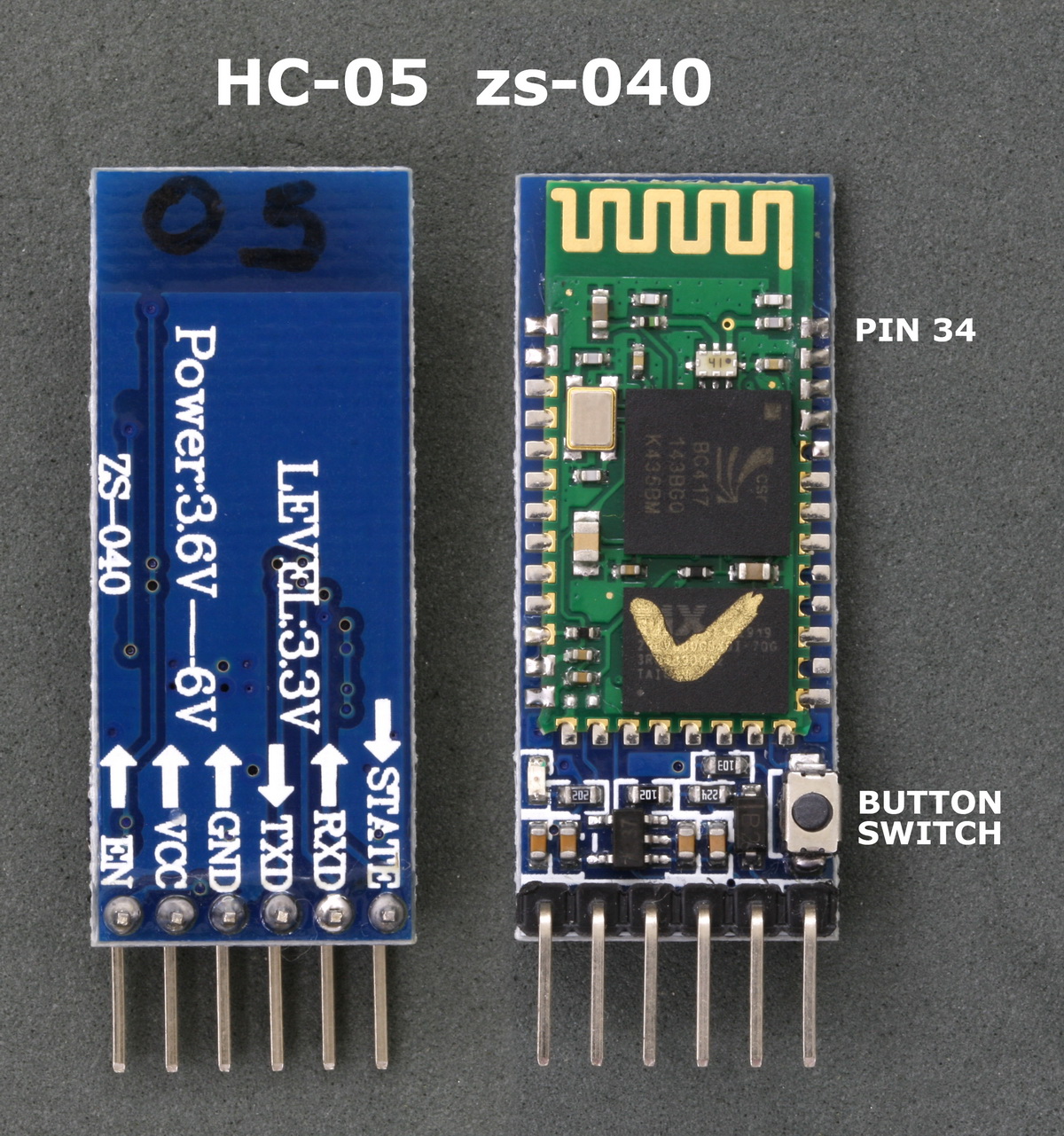
HC-05 marked as zs-040
Firmware version = 2.0-20100601
I have what appears to be the exact same module. I just got it a few weeks ago and have been playing around with it and am far from an expert in it. But I can verify that certain AT commands indeed only work with pin 32 is high (or the tiny button is pressed, which makes pin 32 go high). The datasheet for the HC-05 board itself verifies this, although I don't recall if it specifies which commands require that pin 32 remain high.
Unfortunately the EN header pin isn't wired to pin 32, so you can't use it to keep pin 32 high. You need to either keep the button pressed, or solder or clip a wire whose other end is connected to 3.3V (which I think EN is at when the board is powered, but verify this with a multimeter first to make sure). If you just need to enter a few AT commands it's probably easiest, if awkward, to keep the button pressed, since you generally don't need to change settings that often.
As an aside, I can say that it's been a royal pain figuring out how this board works and getting it to work. I was able to get it into command mode and enter AT commands fairly easily, but actually establishing serial communication with my PC was a nightmare. I was using a tiny USB Bluetooth dongle to enable Bluetooth on my PC, and it turned out that the drivers it came with either didn't fully support Bluetooth, or weren't working properly.
I had to download and install the Toshiba Bluetooth driver, which finally enabled serial communications and allowed me to view my Arduino's serial output in the IDE serial terminal window. However, I still haven't been able to upload sketches via Bluetooth, even after following online instructions for how to do this that used the STATE header pin to reset the Arduino via a 100nF capacitor. Not a huge issue, but still annoying.
I have not had the problem myself but pin 34 is connected to the button, so it sounds like your button is dodgey, and you are bypassing it to get a result.
I was about to refer you to the Martyn Currey website, as he is the heavyweight on matters like this, but I guess that is not necessary..........
OK, so it seems to be standard that pin 34 needs to be HIGH rather than an exception (I'm not so special after all)
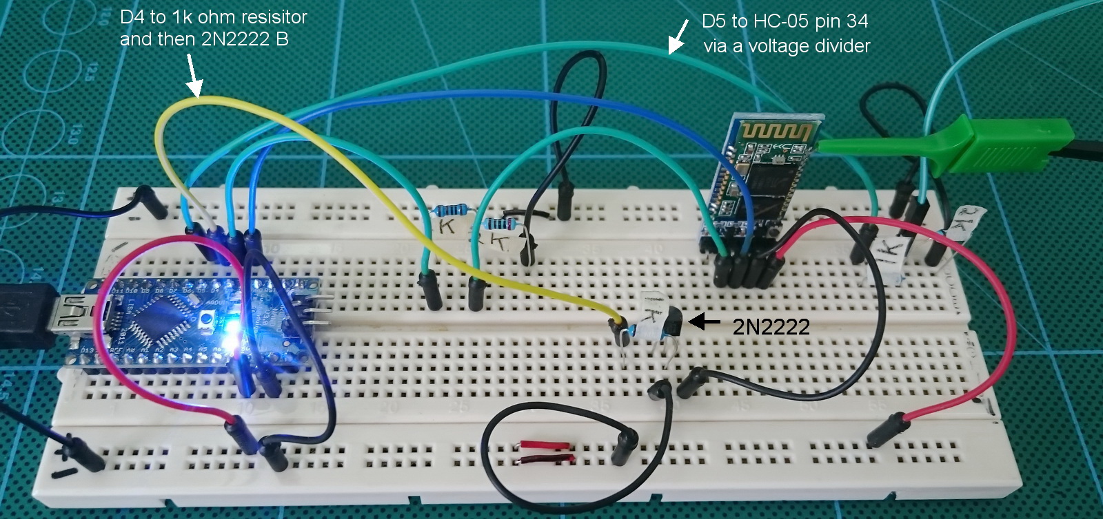
I have had a few thoughts about adding an on/off switch to bring pin 34 HIGH. I did think about replacing the button switch with a mini DIP switch but I'm not sure my soldering skills are up to the task. I may just make my own breakout board on perf board that adds a connection directly to the pin. I want to remove all manual operations and want control everything from the Arduino. I have a breadboard set up that does this including a transistor allowing the Arduino to turn the HC-05 on and off. I could also also voltage convertors at the same time; 5v to 3.3v for the RX pin and pin 34) making it fully self contained.
I think the uploading a sketch via Bluetooth users a different module. The STATE pin on the zs-040 is connected to LED2 (not physically present on the modules) and goes HIGH when a connection is established (or maybe that is what they used). You can test this simply by putting an LED on it.
Nick_Pyner:
I have not had the problem myself but pin 34 is connected to the button, so it sounds like your button is dodgey, and you are bypassing it to get a result.
I was about to refer you to the Martyn Currey website, as he is the heavyweight on matters like this, but I guess that is not necessary..........
He seems to be OK for basic connection stuff using slave mode. Not so hot with Master mode. He did get a HC-05 talking to a HC-06 when the HC-05 was configured to pair with any address but that was automatic and didn't require much from the user.
I didn't find any reference to setting pin34 high to get commands to work (must have not read the documentation properly) and discovered it by accident. I had always assumed things like AT+NAME? didn't work on the modules I had...
I have seen mention of the need to keep pin 34 (not pin 32 as I wrote above mistakenly) high to be able to use some of the AT commands. I've tested it myself to verify this. There's a document often referred to as the HC-05 manual or such, dated April 2011, that mentions this.
And I agree that the momentary push button should have been a DIP or micro switch, to facilitate this. I thought about soldering on a switch, but decided against it as my soldering skills and equipment would likely ruin the board and I'm not going to need to use those AT commands that often. I'll just keep the button pressed with one hand while typing with the other.
Also, pin 32 is connected to the STATE pin, and is what you need to connect to the Arduino's Reset pin via a 100nF capacitor to automatically upload sketches via Bluetooth. You have to first set pin 32/STATE to go LOW (not HIGH) when a connection is made, via one of the AT commands. However I was unable to make this work despite following instructions I came across online here:
If you figure out how to make this work, please let us know!
Nick_Pyner:
I have not had the problem myself but pin 34 is connected to the button, so it sounds like your button is dodgey, and you are bypassing it to get a result.
I was about to refer you to the Martyn Currey website, as he is the heavyweight on matters like this, but I guess that is not necessary..........
I don't think his button is malfunctioning. The issue is whether you need to press the button briefly upon powering the HC-05, or keep it pressed the whole time, to use the entire AT command set. The latter is actually the case, as per pages 3-4 of this document:
MartynC:
My mistake was thinking that since the button press got me in to AT mode at start up I didn't need to keep pin 34 HIGH.
It's an easy "mistake" to make and I made it myself as the "instructions" aren't very clear on this. Just use whatever AT commands you need to use until you come across one that doesn't respond unless you keep the button pressed, and you'll know which ones require this.
Fortunately, you don't actually have to keep the button pressed the whole time to use these "extended" AT commands, only when you have to use them. So you can press it briefly on power-up to get the HC-05 into command mode, and then re-press it and keep it pressed when you need to enter these "extended" commands.
I found it easier to first type the command, then press the button and keep it pressed, then hit enter. A pain, but not too bad given that you generally don't have to enter AT commands often. If you do, or need to enter them programmatically, then you have to look at more permanent solutions, like a switch or soldering a wire to Pin 34, or perhaps building a small breakout board.
I actually built such a board to do level shifting on the Rx pin, so that I could connect it to a 5V Arduino and not have its Tx pin fry the HC-05's Rx pin. It wouldn't be that difficult to connect pin 34 to this board in case I have a need for it.
It's just a small piece of perf board with a 6 pin female angle header and a 6 pin male angle header, with the 4 middle pins wired to each other except the Arduino Tx-HC-05 Rx pins, which have a 1k/2.2k voltage divider circuit between then to shift the voltage down to ~3.3v.
habanero:
I have seen mention of the need to keep pin 34 (not pin 32 as I wrote above mistakenly) high to be able to use some of the AT commands. I've tested it myself to verify this. There's a document often referred to as the HC-05 manual or such, dated April 2011, that mentions this.
And I agree that the momentary push button should have been a DIP or micro switch, to facilitate this. I thought about soldering on a switch, but decided against it as my soldering skills and equipment would likely ruin the board and I'm not going to need to use those AT commands that often. I'll just keep the button pressed with one hand while typing with the other.
Also, pin 32 is connected to the STATE pin, and is what you need to connect to the Arduino's Reset pin via a 100nF capacitor to automatically upload sketches via Bluetooth. You have to first set pin 32/STATE to go LOW (not HIGH) when a connection is made, via one of the AT commands. However I was unable to make this work despite following instructions I came across online here:
If you figure out how to make this work, please let us know!
I haven't tried uploading sketches, I may give it a try at the weekend if I get time.
Just had a play with the STATE pin and AT+POLAR. This does actually change the polarity of the pin. I kind of expected it to simply reverse when the LED was on or off (or maybe they are just the same thing. I wouldn't know).
MartynC:
I haven't tried uploading sketches, I may give it a try at the weekend if I get time.
Just had a play with the STATE pin and AT+POLAR. This does actually change the polarity of the pin. I kind of expected it to simply reverse when the LED was on or off (or maybe they are just the same thing. I wouldn't know).
It doesn't change the polarity of the pin, just when it goes high. High is still +3.3V, regardless of this setting. You can still make the LED turn on when the board is enabled if you change this setting, but by connecting its cathode to pin 32, not the anode, so that pin 32 is now a current sink, not a source. I'm guessing that that's the purpose of the POLAR command, for situations that call for such reverse wiring.
Step 2 of this instructable shows how to wire it for programming with an Uno.
After programming it, if you are then going to pair the Bluetooth with something and communicate with the Uno you would then swap positions of the RX and TX wires. The wiring should be same as in step 4, the Pro Mini is same wiring as Uno.
dmjlambert:
Step 4, I almost forgot, you don't need the State wire to DTR, because there is no DTR pin on the UNO. That wire is only used for auto reset anyway.