The way I've been thinking this with the research I've done so far...
Playstation 2 controller for input (10 buttons, 8 way joypad and 2 analogue joysticks)
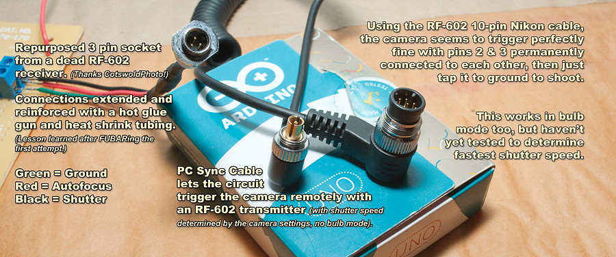
3 Pin output socket stolen from a Yongnuo RF-602 receiver (then I can trigger Nikon, Canon or other just by switching out a £3 cable)
4x20 LCD Panel (just arrived today) so I can see what settings I'm setting, and how far through the sequence I'm shooting)
1x Stepper motor for the slider truck to go along the rail
2x Stepper or Servo motors (haven't decided which route to go yet) for pan/tilt head
On the 3-pin socket from the RF-602 receiver, one pin is for AF, one is for the shutter release, and one is for ground. You need to connect gnd+AF before you can trip the shutter, but with the body set in manual focus mode, it doesn't do anything (except satisfy the requirement of being connected when you connect gnd+shutter). The AF + Shutter pins can actually be connected together so you trip both simultaneously. So, it only uses one pin + gnd on the Arduino. The code just sends it high, then 50ms later sets it low (I'm using millis() to check the time, so that my intervals are accurate and I don't have it locked up using delay()s). You need the 50ms delay to make sure that the LCD turns off and the camera actually takes the shot.
Really, I probably should be using 2 pins and controlling the AF and Shutter pins separately (then I don't need the 50ms delay before setting the pin LOW and the timings would be even more accurate), but until I know for sure I can afford to spare that extra pin, this method works. Btw, for those who shoot Nikon and are curious, regardless of whether I used 1 or 2 pins, the fastest shutter speed I could get the camera to shoot on bulb mode using the 10-pin socket is 1/6th of a second (even if it was only connected for an instant).
4 Pins for the Playstation 2 controller (figured I'd go for this one, then it'd give me an easy wireless option for the future, and it gives a lot of buttons for scrolling through menus and changing settings as well as the 2 analogue joysticks to control both the truck that runs across the slider rail and the pan/tilt head).
The 4x20 LCD panel is just because I'm greedy, I like bigger screens :D, so that's another 2 or 3 pins.
Still figuring out the motor stuff, so not sure how many pins that'll end up using. But, I'm thinking I'll have all I need on an Uno. If not, I suppose I'll just have to get a Mega. 
This is the code so far, and it seems to work ok. I probably could get away with setting triggerInterval as an unsigned int, as I rarely shoot at intervals shorter than 2 seconds, but I set it as a float in case I wanted 0.5 second intervals (if I hook it up to the D300s I can theoretically go as as fast as 0.125 intervals)
// triggerInterval is the number of seconds between shots (in seconds)
float triggerInterval = 3;

// The trigger pin for the shutter
const int triggerPin = 13;

// Time last shot was taken
unsigned long prevshotTime = 0;

// Is the shutter open, false by default
boolean shutterOpen = false;

void setup() {
  // Setup the triggerPin as an output
  pinMode(triggerPin, OUTPUT);
}

void loop() {
  // Store the current time
  unsigned long currentshotTime = millis();

  if (currentshotTime - prevshotTime > triggerInterval*1000) {
    // Store the time the shot was taken so we can compare in the future
    prevshotTime = currentshotTime;
    // Open the shutter, and set the shutterOpen boolean true.
    digitalWrite(triggerPin, HIGH);
    // Finally set the shutter open
    shutterOpen = true;
  }
  if ((currentshotTime > (prevshotTime + 50)) && (shutterOpen == true)) {
    // Turn the LED off, and set the shutterOpen boolean false.
    digitalWrite(triggerPin, LOW);
    // Set the shutter closed
    shutterOpen = false;
  }
}
Next job, as my HD44780 & 74HC164 shift registers arrived today, is to get it outputting stuff to the LCD, so I can keep a count of how many shot's it's taken since the device was turned on. Hopefully my Playstation 2 controller will turn up tomorrow or Monday and I can setup basic start, stop and reset buttons.