Can not receive CAN DATA from Arduino UNO with MCP2515 Module.

Hi,
I'm trying to receive CAN DATA from Arduino UNO with MCP2515 Module.
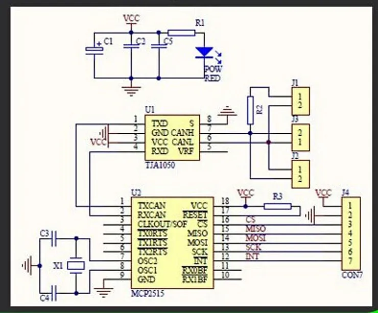
I'm not using CAN-BUS Shield and am only using MCP2515 Module(MCP2515 CAN Controller with TJA1050 CAN transceiver. (Attachment #2))
http://www.aliexpress.com/item/MCP2515-CAN-Bus-Module-Board-TJA1050-Receiver-SPI-For-51-MCU-ARM-Controller-NEW/32581650373.html?spm=2114.01010208.8.8.aabjPj

I think that even though I do not use CAN-BUS Shield, I should be able to receive CAN DATA through the MCP2515 module because it includes MCP2515 CAN controller and TJA1050 CAN transceiver.. Is it right?

Here is my test environments:

  1. Arduino setting: Attachment #1
    OBD2 16pin cable => 6pin(CAN HIGH) and 14pin(CAN LOW) => MCP2515 CAN Module => Arduino UNO

  2. CAN Module: Attachment #2
    MCP2515 CAN Controller with TJA1050 CAN transceiver.
    http://www.aliexpress.com/item/MCP2515-CAN-Bus-Module-Board-TJA1050-Receiver-SPI-For-51-MCU-ARM-Controller-NEW/32581650373.html?spm=2114.01010208.8.8.aabjPj

  3. Vehicle : VW Tiguan

I connected several pins between with Arduino and MCP2515 module like below:
Arduino MPC2515 module
5V VCC
GND GND
13 SCK
12 SO
11 SI
10 CS
2 INT

I downloaded MCP_CAN_LIB source files.

And I opened a "receive" example of MCP_CAN_LIB from Arduino IDE and initialized like "CAN0.begin(CAN_500KBPS, MCP_8MHz)" because my chinese clone MCP2515 moudule is using 8 Mhz crystal.

But I could not receive any CAN DATA.
The function "digitalRead(2)" always returns HIGH..

Has anyone got this problem?

// demo: CAN-BUS Shield, receive data
#include <mcp_can.h>
#include <SPI.h>

long unsigned int rxId;
unsigned char len = 0;
unsigned char rxBuf[8];

MCP_CAN CAN0(10);                               // Set CS to pin 10


void setup()
{
  Serial.begin(115200);
  CAN0.begin(CAN_500KBPS, MCP_8MHz);                       // init can bus : baudrate = 500k 
  pinMode(2, INPUT);                            // Setting pin 2 for /INT input
  Serial.println("MCP2515 Library Receive Example...");
}

void loop()
{
    if(!digitalRead(2))                         // If pin 2 is low, read receive buffer
    {
      CAN0.readMsgBuf(&len, rxBuf);              // Read data: len = data length, buf = data byte(s)
      rxId = CAN0.getCanId();                    // Get message ID
      Serial.print("ID: ");
      Serial.print(rxId, HEX);
      Serial.print("  Data: ");
      for(int i = 0; i<len; i++)                // Print each byte of the data
      {
        if(rxBuf[i] < 0x10)                     // If data byte is less than 0x10, add a leading zero
        {
          Serial.print("0");
        }
        Serial.print(rxBuf[i], HEX);
        Serial.print(" ");
      }
      Serial.println();
    }
}

Hi Oasis,

I am about to try a very similar set up with a 2007 VW Polo. (I also own a Tiguan TDI :slight_smile: ).

Have you made any progress? Your request for assistance does not appear to have been heard?

I have ordered the same MCP2515 board and I have a spare Arduino Micro-Pro that I hope to be able to capture events on the car network to make my Car Radio more automatic. EG turn off when key removed, dim screen when headlights are on. I am not looking to sample any other data at this stage.

My Polo radio connection has the 2 +-CAN-Bus wires in the loom so I am hoping to be able to tap into them.

Perhaps we can work together? Thank you for information above. I will use it to get started myself.

Cheers, Rob

The code should work with a MCP2510, MCP2515, and an MCP25625, but I have only confirmed it on the latter two ICs. Additionally, I have tested the library with that very module you linked to and recently infact.

When you tried the receive example, did you have it connected to the vehicle with the key-switch ON (engine OFF)?

1 Like

Hi Cory

Im trying to use your library to fetch data from a steering angle sensor, data bus it's on is running at 615.3846153846154 Kbit. I tried to modify your library like this;

mcp_can_dfs.h

#define MCP_16MHz_615kBPS_CFG1 (0x00)
#define MCP_16MHz_615kBPS_CFG2 (0xA4)
#define MCP_16MHz_615kBPS_CFG3 (0x01)

My shield is running at 16Mhz and I calculated those values using the spreadsheet included with your library, with BRP set to 0 i get a Time Quantum Max of 13, but I'm not sure I understand it all completely so right now my calculations are pure guesswork.

I tried it in car using the example CAN_recive but with my 615Kbit mod, only result i had was that I managed to get all sorts of warnings on on the cars dashboard when I had the Arduino powered on :slight_smile:

//Fredrik

Fredrik,

It looks good on my end with your sample point being at 84.62%. The only two items I would change is setting the Sample Mode (SAM) bit to change the bit sampling from one sample to three averaged samples, and increase the Synchronization Jump Width (SJW) to 2, these will only help increase reliability but most likely wont fix your issue. Outside of this, are you positive this is the baudrate and are you positive you have CAN_H and CAN_L correct (reverse them if not)?

The register modifications I mentioned would look like:

#define MCP_16MHz_615kBPS_CFG1 (0x80)
#define MCP_16MHz_615kBPS_CFG2 (0xE4)
#define MCP_16MHz_615kBPS_CFG3 (0x01)

Cory, thanks for helping out.

The CAN-bus I'm connecting to is the one found on Saab Trionic 5 and 7 engine management systems. It's quite well documented here: http://www.trionictuning.com.
People active on that forum have written software to communicate with those ECU's over CAN and this is where I found the 615... kbps value. I need this to get the steering angle signal and convert it to an analog signal understandable by a Siemens ECU controlling an AWD system.

/Fredrik

I have the same setup (Arduino Uno -> MCP2515 -> TJA1050 -> ODB22 pin 6 and 14), and trouble receiving messages from my Peugeot 207.

Connection from the Arduino to the MCP2515 seems to be just fine, but I'm just not receiving any messages. Now I see the register modifactions mentioned here, but I don't really understand them. Could those also be my problem? Do I need to modify the library as well?

Are you positive this vehicle has CAN? The best way to tell is whether there is a physical contact for pins 6 and 14 on the OBDII port of the vehicle.

What baud rates have you tried? FYI, 250k & 500k are OBDII standards.

Does the board you have come terminated? Remove it if so! OBDII does not allow a scan tool to have a DC termination. Also, keep in mind the cable length shouldn't be any longer than 1 meter.

Have you tried swapping the CAN connections going to your the OBDII port? Eg, the polarity is wrong: CAN_H and CAN_L are reversed and this condition needs corrected.

1 Like

coryjfowler:
Are you positive this vehicle has CAN? The best way to tell is whether there is a physical contact for pins 6 and 14 on the OBDII port of the vehicle.

Yes, I'm sure. It is a 2008 car and it's mentioned in different specs. Furthermore, some people have been able to hack into the CAN bus for this vehicle, as can ben seen on Youtube (unfortunately they don't respond to my messages for more information).

coryjfowler:
What baud rates have you tried? FYI, 250k & 500k are OBDII standards.

Yes, I have tried both.

coryjfowler:
Does the board you have come terminated? Remove it if so! OBDII does not allow a scan tool to have a DC termination. Also, keep in mind the cable length shouldn't be any longer than 1 meter.

The board has a jumper to terminate the connection. I've used the board unterminated. See these schematics.

coryjfowler:
Have you tried swapping the CAN connections going to your the OBDII port? Eg, the polarity is wrong: CAN_H and CAN_L are reversed and this condition needs corrected.

I have tried, but it actually made the instruments go crazy etc, and I got various diagnostic errors on my dashboard (which disappeared after running the car for a while).

Have you tried sending an OBD-II PID request? I'd try at 250k first. It could just be that the port has a CAN bus dedicated for OBD-II and nothing is broadcast over it. Outside of that I would investigate your hardware. The fact that reversing the polarity caused an issue tells me the port is active in some sense.

coryjfowler:
Have you tried sending an OBD-II PID request? I'd try at 250k first. It could just be that the port has a CAN bus dedicated for OBD-II and nothing is broadcast over it. Outside of that I would investigate your hardware. The fact that reversing the polarity caused an issue tells me the port is active in some sense.

That could very well be possible. I haven't tried sending an ODB-II PID. Forgive me if it's a stupid question, but how do I do this with the Arduino and MCP2515? I'm only familiar with sending serial commands via an ELM327.

You can give this a whirl, it will probably be the weekend before I can load it on one of my boards and throw it at my car.

/* CAN OBD & UDS Simple PID Request
 *
 *  Currently requests PID 0x00 at a 1 second interval and
 *  displays all received CAN traffic to the terminal at 115200.
 *
 *  Written By: Cory J. Fowler  April 5th, 2017
 *
 *  (Disclaimer: Standard IDs are currently UNTESTED against a vehicle)
 *
 */

#include <mcp_can.h>
#include <SPI.h>

#define standard 0
// 7E0/8 = Engine ECM
// 7E1/9 = Transmission ECM
#if standard == 1
  #define LISTEN_ID 0x7EA
  #define REPLY_ID 0x7E0
  #define FUNCTIONAL_ID 0x7DF
#else
  #define LISTEN_ID 0x98DAF101
  #define REPLY_ID 0x98DA01F1
  #define FUNCTIONAL_ID 0x98DB33F1
#endif

// CAN TX Variables
unsigned long prevTx = 0;
unsigned int invlTx = 1000;
byte txData[] = {0x02,0x01,0x00,0x55,0x55,0x55,0x55,0x55};

// CAN RX Variables
unsigned long rxID;
byte dlc;
byte rxBuf[8];
char msgString[128];                        // Array to store serial string

// CAN Interrupt and Chip Select Pins
#define CAN0_INT 2                              /* Set INT to pin 2 (This rarely changes)   */
MCP_CAN CAN0(9);                                /* Set CS to pin 9 (Old shields use pin 10) */


void setup(){

  Serial.begin(115200);
  while(!Serial);
 
  // Initialize MCP2515 running at 16MHz with a baudrate of 500kb/s and the masks and filters disabled.
  if(CAN0.begin(MCP_STDEXT, CAN_500KBPS, MCP_16MHZ) == CAN_OK)
    Serial.println("MCP2515 Initialized Successfully!");
  else{
    Serial.println("Error Initializing MCP2515... Permanent failure!  Check your code & connections");
    while(1);
  }

//
//  // Allow all Standard IDs
//  CAN0.init_Mask(0,0x00000000);                // Init first mask...
//  CAN0.init_Filt(0,0x00000000);                // Init first filter...
//  CAN0.init_Filt(1,0x00000000);                // Init second filter...
//  // Allow all Extended IDs
//  CAN0.init_Mask(1,0x80000000);                // Init second mask...
//  CAN0.init_Filt(2,0x80000000);                // Init third filter...
//  CAN0.init_Filt(3,0x80000000);                // Init fouth filter...
//  CAN0.init_Filt(4,0x80000000);                // Init fifth filter...
//  CAN0.init_Filt(5,0x80000000);                // Init sixth filter...

#if standard == 1
  // Standard ID Filters
  CAN0.init_Mask(0,0x7F00000);                // Init first mask...
  CAN0.init_Filt(0,0x7DF0000);                // Init first filter...
  CAN0.init_Filt(1,0x7E10000);                // Init second filter...

  CAN0.init_Mask(1,0x7F00000);                // Init second mask...
  CAN0.init_Filt(2,0x7DF0000);                // Init third filter...
  CAN0.init_Filt(3,0x7E10000);                // Init fouth filter...
  CAN0.init_Filt(4,0x7DF0000);                // Init fifth filter...
  CAN0.init_Filt(5,0x7E10000);                // Init sixth filter...

#else
  // Extended ID Filters
  CAN0.init_Mask(0,0x90FF0000);                // Init first mask...
  CAN0.init_Filt(0,0x90DA0000);                // Init first filter...
  CAN0.init_Filt(1,0x90DB0000);                // Init second filter...

  CAN0.init_Mask(1,0x90FF0000);                // Init second mask...
  CAN0.init_Filt(2,0x90DA0000);                // Init third filter...
  CAN0.init_Filt(3,0x90DB0000);                // Init fouth filter...
  CAN0.init_Filt(4,0x90DA0000);                // Init fifth filter...
  CAN0.init_Filt(5,0x90DB0000);                // Init sixth filter...
#endif

  CAN0.setMode(MCP_NORMAL);                      // Set operation mode to normal so the MCP2515 sends acks to received data.

  // Having problems?  ======================================================
  // If you are not receiving any messages, uncomment the setMode line below
  // to test the wiring between the Ardunio and the protocol controller.
  // The message that this sketch sends should be instantly received.
  // ========================================================================
  //CAN0.setMode(MCP_LOOPBACK);

  pinMode(CAN0_INT, INPUT);                          // Configuring pin for /INT input
 
  Serial.println("Simple CAN OBD-II PID Request");
}

void loop(){

  if(!digitalRead(CAN0_INT)){                         // If CAN0_INT pin is low, read receive buffer
 
    CAN0.readMsgBuf(&rxID, &dlc, rxBuf);             // Get CAN data
   
    // Display received CAN data as we receive it.
    if((rxID & 0x80000000) == 0x80000000)     // Determine if ID is standard (11 bits) or extended (29 bits)
      sprintf(msgString, "Extended ID: 0x%.8lX  DLC: %1d  Data:", (rxID & 0x1FFFFFFF), dlc);
    else
      sprintf(msgString, "Standard ID: 0x%.3lX       DLC: %1d  Data:", rxID, dlc);
 
    Serial.print(msgString);
 
    if((rxID & 0x40000000) == 0x40000000){    // Determine if message is a remote request frame.
      sprintf(msgString, " REMOTE REQUEST FRAME");
      Serial.print(msgString);
    } else {
      for(byte i = 0; i<dlc; i++){
        sprintf(msgString, " 0x%.2X", rxBuf[i]);
        Serial.print(msgString);
      }
    }
       
    Serial.println();
  }
 
  /* Every 1000ms (One Second) send a request for PID 00           *
   * This PID responds back with 4 data bytes indicating the PIDs  *
   * between 0x01 and 0x20 that are supported by the vehicle.      */
  if((millis() - prevTx) >= invlTx){
    prevTx = millis();
    if(CAN0.sendMsgBuf(FUNCTIONAL_ID, 8, txData) == CAN_OK){
      Serial.println("Message Sent Successfully!");
    } else {
      Serial.println("Error Sending Message...");
    }
  }
}

Edit 20170514: Tested and fixed some bugs. I can confirm that extended ID mode (#define standard 0) works with my vehicle and I unfortunately do not have access to a vehicle that operates in standard ID mode to confirm with.

Thanks a lot. I've tried your code (just changed 16MHz -> 8MHz, INT on pin 9 -> pin 10).

However, I'm not getting any output other than just the setup of the module. My knowledge in this field is very limited, but could the 8MHz crystal be the problem? Maybe some of the values in the timing registers for 8MHz?

Entering Configuration Mode Successful!
Setting Baudrate Successful!
MCP2515 Initialized Successfully!
Starting to Set Mask!
Setting Mask Successful!
Starting to Set Filter!
Setting Filter Successfull!
Starting to Set Filter!
Setting Filter Successfull!
Starting to Set Mask!
Setting Mask Successful!
Starting to Set Filter!
Setting Filter Successfull!
Starting to Set Filter!
Setting Filter Successfull!
Starting to Set Filter!
Setting Filter Successfull!
Starting to Set Filter!
Setting Filter Successfull!
Simple CAN OBD-II PID Request

I have tested some of the more common 8MHz baud rate configuration register settings against a Peak adapter and a Vector VN1610, so I trust those to be good.

I edited the send function to give some indication about when a message was sent or if there was an error while sending. If there is no error while sending and your car doesn't exhibit any signs we are corrupting signals (like when the CAN line polarity was reversed), it should be safe to assume the baudrate of 250k is correct. In that case, try changing the 1 in "#define standard 1" to a 0 to try OBD-II with extended IDs. Otherwise, try it again, but only changing the baudrate to 500k.

If you get send errors at both 250k and 500k, change "CAN0.setMode(MCP_NORMAL);" to "CAN0.setMode(MCP_LOOPBACK);". You should see the one packet we transmit come right back and display on the screen. This will confirm your protocol controller is functioning as it should and that it is correctly wired to the Arduino.

If you do not see a received message, check your INT pin connection and the definition for it in the sketch.

If you see the received message while in loop back, I would check the connection between the protocol controller and the transceiver making sure that there is continuity between the ICs and that there are not shorts to ground, power, or another signal.

coryjfowler:
I have tested some of the more common 8MHz baud rate configuration register settings against a Peak adapter and a Vector VN1610, so I trust those to be good.

Ok, it was just a thought, because 16MHz seem to be 'standard'.

coryjfowler:
I edited the send function to give some indication about when a message was sent or if there was an error while sending. If there is no error while sending and your car doesn't exhibit any signs we are corrupting signals (like when the CAN line polarity was reversed), it should be safe to assume the baudrate of 250k is correct. In that case, try changing the 1 in "#define standard 1" to a 0 to try OBD-II with extended IDs. Otherwise, try it again, but only changing the baudrate to 500k.

I got the error message, both with 250k and 500k. I got the error message both when connected to the car, and when not connected to a CAN bus at all.

I measured the voltage with a multimeter on the ODBII port in the car, and when not connected to my project, the voltages are DC 2.56V both on H and L.

coryjfowler:
If you get send errors at both 250k and 500k, change "CAN0.setMode(MCP_NORMAL);" to "CAN0.setMode(MCP_LOOPBACK);". You should see the one packet we transmit come right back and display on the screen. This will confirm your protocol controller is functioning as it should and that it is correctly wired to the Arduino.

If you do not see a received message, check your INT pin connection and the definition for it in the sketch.

If you see the received message while in loop back, I would check the connection between the protocol controller and the transceiver making sure that there is continuity between the ICs and that there are not shorts to ground, power, or another signal.

I actually see the received message in loopback, so that seems to work. I have also checked the PCB for continuity between the MCP2515 and the TJA1050. Also, the VCC and GND connections seem to be working properly. I'm wondering however if maybe the VCC for the transceiver chip is too low, as I'm measuring 4.01V over the VCC and GND. The datasheet says 4.75V minimum. But maybe it is just normal to measure a lower voltage when the IC is running?

Yes, I would say that voltage definitely needs fixed. It should be much closer to 5.0 than that.

The (first) module I used may actually be faulty. I have acquired a second module, which gives normal values on the VCC voltages and I actually am receiving messages now!

However, with your code, I'm receiving messages, but the sending of the message keeps failing, like below. The CAN_receive example gives me just the Standard ID messages, so that seems to work now.

Entering Configuration Mode Successful!
Setting Baudrate Successful!
MCP2515 Initialized Successfully!
Starting to Set Mask!
Setting Mask Successful!
Starting to Set Filter!
Setting Filter Successfull!
Starting to Set Filter!
Setting Filter Successfull!
Starting to Set Mask!
Setting Mask Successful!
Starting to Set Filter!
Setting Filter Successfull!
Starting to Set Filter!
Setting Filter Successfull!
Starting to Set Filter!
Setting Filter Successfull!
Starting to Set Filter!
Setting Filter Successfull!
Simple CAN OBD-II PID Request
Standard ID: 0x2F5       DLC: 3  Data: 0x5E 0x00 0x80
Error Sending Message...
Standard ID: 0x2F5       DLC: 3  Data: 0x4F 0x00 0x80
Error Sending Message...
Standard ID: 0x488       DLC: 8  Data: 0x3D 0x00 0x70 0x00 0x1E 0x3C 0xFF 0x3D
Error Sending Message...
Standard ID: 0x612       DLC: 5  Data: 0x73 0x20 0x01 0x36 0x00
Error Sending Message...
Standard ID: 0x38D       DLC: 7  Data: 0x00 0x00 0x00 0x00 0xAF 0xD1 0x00
Error Sending Message...
Standard ID: 0x432       DLC: 6  Data: 0x81 0x59 0x48 0xFE 0x00 0x00
Error Sending Message...
Standard ID: 0x348       DLC: 8  Data: 0x00 0x4F 0x2D 0x44 0xC0 0x01 0x00 0x40
Error Sending Message...
Standard ID: 0x412       DLC: 8  Data: 0x18 0x00 0x00 0x00 0x00 0x3C 0x0A 0x00
Error Sending Message...
Standard ID: 0x072       DLC: 5  Data: 0x02 0x00 0x00 0x00 0x00
Error Sending Message...
Standard ID: 0x208       DLC: 8  Data: 0x00 0x00 0x21 0x00 0x0C 0xFF 0xFF 0x4F
Error Sending Message...
Standard ID: 0x2F5       DLC: 3  Data: 0xC7 0x00 0x80
Error Sending Message...
Standard ID: 0x348       DLC: 8  Data: 0x00 0x4F 0x2D 0x44 0xC0 0x01 0x00 0x40
Error Sending Message...
Standard ID: 0x2F5       DLC: 3  Data: 0x4F 0x00 0x80
Error Sending Message...
Standard ID: 0x208       DLC: 8  Data: 0x00 0x00 0x21 0x00 0x0C 0xFF 0xFF 0x4F
Error Sending Message...
Standard ID: 0x2F5       DLC: 3  Data: 0x03 0x00 0x80
Error Sending Message...
Standard ID: 0x2F5       DLC: 3  Data: 0x7C 0x00 0x80
Error Sending Message...
Standard ID: 0x2F5       DLC: 3  Data: 0x6D 0x00 0x80
Error Sending Message...
Standard ID: 0x348       DLC: 8  Data: 0x00 0x4F 0x2D 0x44 0xC0 0x01 0x00 0x40
Error Sending Message...
Standard ID: 0x30D       DLC: 8  Data: 0x00 0x00 0x00 0x00 0x00 0x00 0x00 0x00
Error Sending Message...
Standard ID: 0x30D       DLC: 8  Data: 0x00 0x00 0x00 0x00 0x00 0x00 0x00 0x00
Error Sending Message...
Standard ID: 0x30D       DLC: 8  Data: 0x00 0x00 0x00 0x00 0x00 0x00 0x00 0x00
Error Sending Message...
Standard ID: 0x348       DLC: 8  Data: 0x00 0x4F 0x2D 0x44 0xC0 0x01 0x00 0x40
Error Sending Message...
Standard ID: 0x2F5       DLC: 3  Data: 0xC7 0x00 0x80
Error Sending Message...
Standard ID: 0x38D       DLC: 7  Data: 0x00 0x00 0x00 0x00 0xAF 0x1D 0x00
Error Sending Message...
Standard ID: 0x592       DLC: 3  Data: 0x00 0x00 0x00
Error Sending Message...
Standard ID: 0x2F5       DLC: 3  Data: 0x4F 0x00 0x80
Error Sending Message...

Does it send okay in loopback mode? I'd fault the module again if so, since it sounds like the TX CAN connection between the protocol controller and the transceiver might be open or shorted to something.

Glad to see that you're seeing messages from your vehicle though.

I have been working on it a bit more, but I am getting such strange results.

coryjfowler:
Does it send okay in loopback mode? I'd fault the module again if so, since it sounds like the TX CAN connection between the protocol controller and the transceiver might be open or shorted to something.

Glad to see that you're seeing messages from your vehicle though.

Sending of the message in loopback mode does actually work. But it is also working when I just connect two modules with terminators. A 'local' CAN bus with two modules and two arduinos does seem to work just fine. I can send and receive messages on both modules. The voltages on the modules also seem in order.

Radio and steering wheel controls
As mentioned above, I finally got messages on the ODB2 port. However, they don't contain the data I'm looking for, namely the steering wheel controls for the radio (as my project is trying to use the steering wheel buttons to control some media players in the car).

To my understanding, the steering wheel controls work via CAN bus. This can also be seen when looking for [commercially available adapters](http://Peugeot Steering Wheel Interface with RD4 / RT4 With CAN-Bus & Stalk Controls Order RPG001 to retain rear parking sensors. head units compatible with the following Vehicles: Peugeot 307 (2005 onwards) Peugeot 807 (2005 onwards) Peugeot 407 (2005 onwards) Peugeot 207 (2006 onwards) Peugeot 308 (2007 onwards) Peugeot 307 : 2005 Onwards Peugeot 408) and in this specification of peugeot CAN bus messages.

So I tried connecting a module to the CAN bus wires of the radio (per this schematic, for example). But this gave some strange results;

  • First, I measured the voltages of these wires, and they are actually the other way around from the schematics. Connecting by the schematics resulted in random dashboard errors. Connecting the other way around gave no errors, but also not one message. I tried different baud rates, 125k, 250k and 500k
  • The voltage difference in the radio CAN bus wires is much higher than on the ODB2 port. On the radio I'm measuring 4.58V vs 0.34V. On the ODB2 port I'm measuring 3.13V vs 2.36V. So apparently this is not the same CAN bus.

I'm actually quite lost now on what is happening here, and how to proceed :confused:

PS. Sorry to the original poster for 'hijacking' your topic a bit :cold_sweat:

reynard80:
So I tried connecting a module to the CAN bus wires of the radio (per this schematic, for example). But this gave some strange results;

Did those wires appear to be twisted together by chance? That's usually a good indicator of some type of digital bus. Also, its not unheard of for extra CAN buses to be populated on the OBD-II manufacture's discretion pins. My old Escape had two and my new Jeep has three on the port. (I found them via trial and error.)

At this point, I'd say you'd need an oscilloscope to see what is actually going on between your car and the CAN module. Something just isn't right and its interesting that they work fine together, but not with your car.