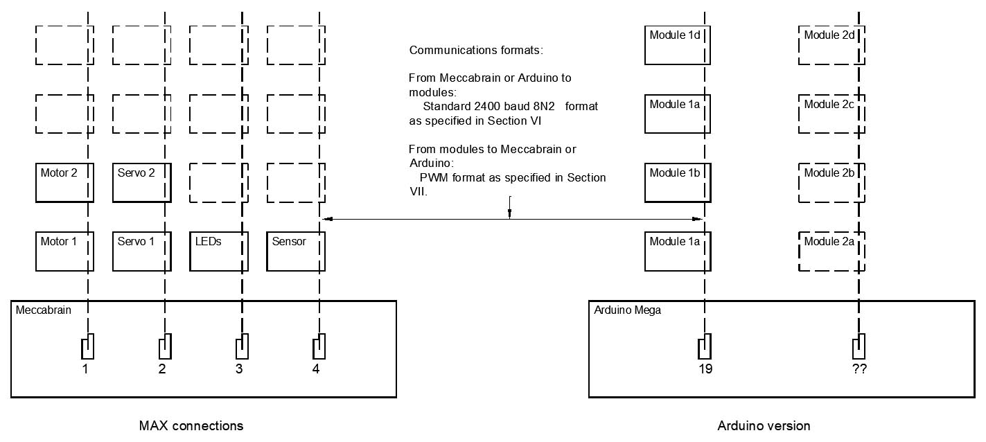
I have come across something weird that I can find no explanation for.
I am developing an application using Serial1 in a Mega to transmit a string of characters to a slave device. The slave accepts 2400 baud, 2 stop bit, no parity, and replies over the same line using a strange semi PWM format - pulse high for < 400 us = LOW; high > 400 us = HIGH. The message string is prescribed as 6 bytes, the first is always 0xFF, there are 4 following bytes, and a checksum/address combination - 6 bytes in all. Each bit is a total 1.1 ms, and there is a start bit of around 1.5 ms. In some cases, there will be no slave response so the system has to accommodate this.
My concept is to use interrupts as much as possible so the Arduino can do processing while the communications is happening. On the completion of the transmission, I want to start a timeout check using one of the 16-bit timers. Initially I set this up for 15 ms, but found that the timer was not correctly synchronised to the end of the transmission.
Code is as follows:
int i=0, phase = 0;
byte message[] = { 0xFF, 0xFE, 0xFE, 0xFE, 0xFE, 0x00 };
byte item, receivedValue;
int receivedBitCount;
int timeOut = 0xA23A;
int messageLength = sizeof(message);
boolean messageSent, transmitFlag, receiveFlag, nextState;
boolean int3Flag, timedOutFlag, readComplete, dataValid;
volatile long intTime;
long pulseStart, pulseWidth;
void setup()
{
  pinMode(18, INPUT);
  pinMode(17, OUTPUT);
  Serial.begin(38400);
  messageSent = LOW;
  transmitFlag = LOW;
  receiveFlag = LOW;
  item = 0;
  Serial.println(messageLength);
  Serial.print(UCSR1A, BIN),Serial.print(" ");Serial.print(UCSR1B, BIN);Serial.print(" ");Serial.println(UCSR1C, BIN);
}

void loop()
{
  switch (phase)
  {
    case 0:
    {
 // Update message details and start sending process
      Serial.println(calcCheckSum(message));
      message[messageLength - 1] = calcCheckSum(message) | (item & 0x0F);
      Serial1Start();
      transmitFlag = HIGH;
      phase = 1;
      break;
    }
    case 1:
    {
 // Write byte to buffer - if done, move on, else go round again
      Serial.print(i); Serial.print(" = ");
      Serial.print(message[i], HEX);Serial.println();
      UDR1 = message[i++];
      if (i > messageLength - 1)
      {
        i = 0;
        phase = 3;
      }
      else phase = 2;
      break;
    }
    case 2:
    {
 // Wait for buffer to be emptied - then write next one
      if (UCSR1A & (1 << UDRE1))
      {
        phase = 1;
      }
      break;
    }
    case 3:
 // Message completed - wait for shift register to be emptied.
    {
      if (UCSR1A & (1 << TXC1))
      {
        phase = 4;
        digitalWrite(17, HIGH);
        transmitFlag = LOW;
      }
      break;
    }
    case 4:
    {
 // Message sent out - disable transmit.  Also increment item ptr.
     UCSR1A = B00000000 | (1 << TXC1);     // Clear TXC1 flag
     UCSR1B = B00000000;                   // Disable transmitter function
     item++;
     if (item > 3) item = 0;
 // Prepare to receive.  Start timer and initialise values.
//     digitalWrite(17, HIGH);
     receivedBitCount = 0;
     receivedValue = 0;
     dataValid = false;
     readComplete = LOW;
     startTimer5();
     Serial.print("  TCCR5A = ");Serial.print(TCCR5A, BIN);Serial.print("  TCCR5B = ");Serial.print(TCCR5B, BIN);
     Serial.print("  TCCR5C = ");Serial.print(TCCR5C, BIN);Serial.print("  TIMSK5 = ");Serial.print(TIMSK5, BIN);
     Serial.print("  TIFR5 = ");Serial.println(TIFR5, BIN);
     phase = 5;
     break;
    }
    case 5:
    {
      while (!timedOutFlag)
      {
        Serial.println(TCNT5, HEX);
      }
      if(timedOutFlag)
      {
        digitalWrite(17, LOW);
        readComplete = true;
        phase = 0;
        timedOutFlag = false;
      }
      phase = 6;
     break;
   }
   case 6:
   {
 // Response completed. Disable interrupts.
    stopTimer5();
    stopInt3();
    if (!readComplete) Serial.println(" No response.");
//    Serial.println(receivedValue, BIN);
    phase = 7;
    break;
   }
   case 7:
   {
    delay(10);
    phase = 0;
    break;
   }
  }
// Serial.println(phase);Serial.println(timedOutFlag);
  if (timedOutFlag)
  {
    digitalWrite(17, LOW);
    receivedValue = 0;
    if (!readComplete)
    {
      Serial.println(" No response.");
      readComplete = true;
    }
    timedOutFlag = false;
//    stopTimer5();
    readComplete = true;
    phase = 0;
  }
}

ISR(TIMER5_OVF_vect)
{
  timedOutFlag = HIGH;
  TCNT5 = timeOut;
}

void startTimer5()
{
  TCCR5A = B00000000;     // Normal mode of operaton
  TCCR5B = B00000010;     // Prescale = 1/8 - tick is 2 MHz = 0.5 us
  TCCR5C = B00000000;
  TCNT5 = timeOut;          // 0xFFFF - 0x8ACF = 0x7530 = 30,000 = 15 ms
  TIMSK5 = 1 << TOIE5;    // Enable timer overflow interrupt
  timedOutFlag = LOW;
}

void stopTimer5()
{
  TIMSK5 = 0;             // Disable timer 5 overflow interrupt
  TCCR5B = B00000000;     // Stop timer
}


void Serial1Start()
{
  UBRR1H = 0x01;
  UBRR1L = 0xA0;
  UCSR1A = B00000000;
  UCSR1B = B00001000;
  UCSR1C = B00001110;
}

byte calcCheckSum(byte data[])
{
//  int dataLength = sizeof(data);
  int CS = 0;
  for (int i = 1; i < 5; i++)
  {
    CS = CS + data[i];
  }
  CS = CS + (CS >> 8);
  CS = CS + (CS << 4);
  CS = CS & 0xF0;
  return CS;
}
I'm using a switch statement to handle the various phases. The area of concern is case 4, where I am detecting the sending of the last bit in the transmitted message and then starting Timer 5.
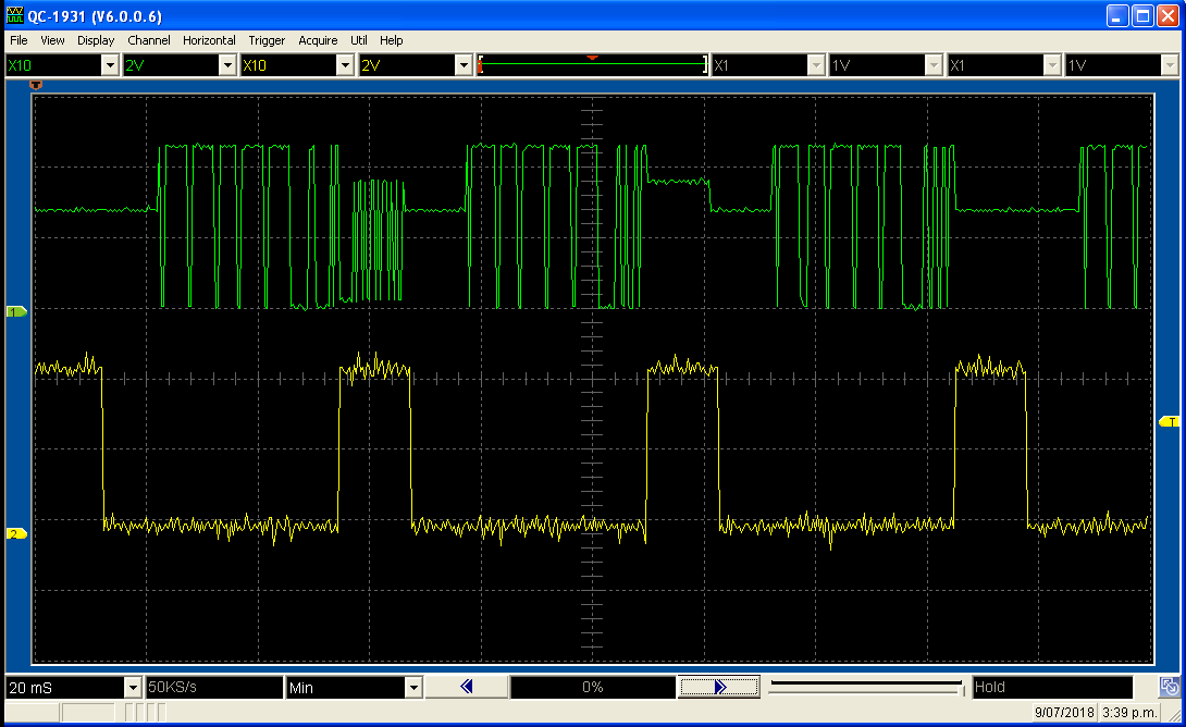
With the timer set to give a 15 ms delay, it was starting after the 4th bit of the 6-bit message instead of waiting till the complete message has been sent. By experimenting, I found that adding an extra 0x00 byte to the end of the message, it was sent and the timer started at the end of the stream as expected. I also altered the timer preset to give a 12 ms timeout, and again it worked as expected.
In the attached photos, the top trace is the traffic on the communications port, and the bottom shows the operation of the timer - HIGH when the timer is running.
I have absolutely no idea what is causing this, and any input from the group will be welcome!

Delay set to 15 ms - showing overall communication stream and timer active period.

Same - detail of change from serial transmission to custom format reception.

As above but with delay set to 12 ms