I've seen a lot of relays rated for 10A, but I'm looking for a 15A relay (1 Channel). The system is a 24V system if thats a factor. I'm located in the USA and I would prefer a US vendor to minimize shipping time. Any help is greatly appreciated!
Basically there will be a 22.2V 15A battery bank with a BMS 6S4P 3.7V 3.2A Li-ion powering a 24V heater (yes, heater won't be 100% effective) controlled by a relay switch. The relay switch will be connected to a 5V Arduino Mega. Hope I answered your question and thanks for the reply!
Is the heater really rated at 333 watts (22.2*15)? Just because the battery is rated at 15A doesn't mean you need a relay for that much current. You size the relay to the load and the load type.
A properly selected mosfet would work but let's first get to the actual specifications. What is the actual heater rated wattage and voltage?
I have attached some documents that may better explain the system. The "0 Watt" bothered me too but the thermal engineer insisted on that heater.
The main goal is to keep an insulated box between 0℃ and 40℃, the Arduino mega will be program to turn the heater on around 5℃ and off around 20℃. The relay is used because the Arduino max output is 5V which is too low for the heater.
Attached to the Arduino is Temp Sensor, Current sensor (iC), and Voltage sensor (VS). The iC and VS will monitor battery and be a able to output that data [A whole other problem].
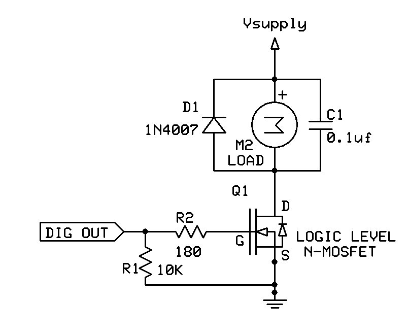
It would be much better to use a logic level MOSFET (for example, this one) instead of a relay, as shown below. That way you can precisely control the power output of the heater using an Arduino PWM output. The diagram is for a motor, but for a heater, you don't need the parallel diode and capacitor.
Or a dedicated 24V driver chip like a BTT6010. That takes care of all the complexity of driving a high-power mosfet and gives you feedback so you can measure how the heater is doing.
You neglected to provide a link to the battery, which I can tell you now is not a 15A battery - there's
no such animal.
15Ah is entirely plausible, that's the capacity rating, not a current rating.
The load is 38 ohms, so as indicated above you have about 0.6A to switch, even a 2N2222 BJT can
just about do that (with a 150 ohm base resistor).
A logic level MOSFET or a darlington are better options (less close to the package heat limit,
especially with a heatsink).
What you will need also is a 1A fuse to protect the wiring and battery in event of a short circuit -
this goes inline with the battery +ve terminal usually, close to the battery. Your 6S LiPo pack
(guessing from the 22.2V rating) is capable of perhaps 100's of amps on a short, this is a fire
hazard and you must protect against this in unattended equipment.