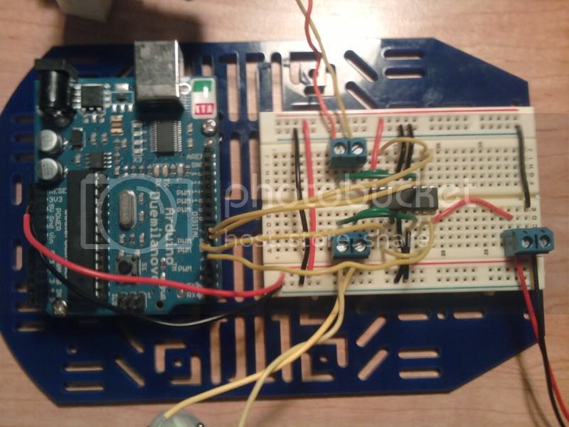
I just want to know whether I am doing something wrong with my H-bridge circuit. I want to control both speed and direction and just want another persons opinion on whether this will control speed and direction here is the pin out:
5v is coming from the Arduino and ground is coming from Arduino
9v connected to pin 8 and ground of the H-bridge
pin 1(enable 1) of H-Bridge is connected to +5v, pin 9(enable 2) of H-bridge is connected to +5v, pin 16(Vss) of H-bridge is connected to +5v
pin 2(input 1) of H-bridge is connected to PWM 5, pin 7(input 2) is connected to pin D4, pin 15(input 4) of H-bridge is connected to PWM 6, and pin 10(input 3) of H-bridge is connected to pin D7.
pins 11(output 3), and 14(output 4) on H-bridge are connected to the terminal block motor B.
pins 3(output 1), and 6(output 2) on H-bridge are connected to the terminal block motor A.
pins 4 and 5 on H-bridge are connected to ground
pins 12, and 13 of H-bridge are connected to ground
found out you need the PWM pin on the enable to control speed so both of the enables are connected to PWM D5 and PWM D6 and I have pin D12 and pin D10 connected to pins 1 and 15 of the H-bridge. here is that pic:
So I think I figured this out but i still want an opinion in order to do it the second way (in reference to the post that precedes this) I would need a through hole inverter (2 of them) or I can do it with six I/O's instead of the 4. any comments would be nice thanks
right now one motor runs (does not run until I add the 9v though I think this is because I need the decoupling cap) but it does not run as expected it runs in one direction at 1 speed.
The problem is you keep posting photos of your circuit. It is very difficult to see what you are doing from this. That is why God invented schematics, so other people can see what you are doing. Post one of those and you might get a response.
No problem I did figure out that speed is working so PWM is fine the only problem is directionmaybe it is my code because I really do think my hardware is correct here is the schematic:
Thanks that is better.
Basically you have not written the code correctly. You need to put both lines to the same level to turn it off and different levels to turn it on. So where so you need to put:-
// Turn motor 1 on
digitalWrite(dir_a1, HIGH);
digitalWrite(dir_b1, HIGH);
// Turn motor 2 off
digitalWrite(dir_a2, LOW);
digitalWrite(dir_b2, LOW);
analogWrite(PWM1, 100);
Note you will not see much of a speed change unless the motor is under load.
I must be tired or something but it turns out my hardware was correct and my software had a few glitches but as I said it works now next up adding hardware inverter