This tank is controlled by any Android device (phone, tablet), via BlueTooth.
The real time video is conveyed via Wi-Fi.
For additional info regarding the Android controller, please refer to the Joystick Bluetooth Commander pages
Quick tips:
Tank is built upon a Dagu Rover 5 base and can be operated in total darkness (IR led's)
Arduino is connected to a Dagu quad driver board
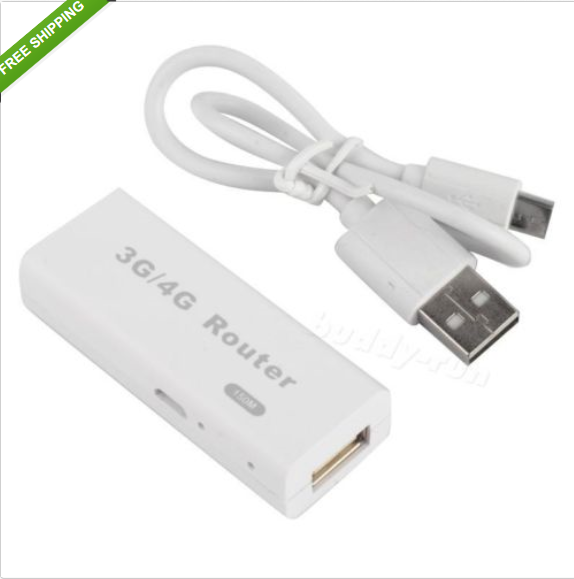
There is an on-board mini router ($9.68 shipped) to establish a direct WiFi connection with the tablet
The 3 white platforms are CNC'ed plywood plates, assembled with M3 Brass Standoff Spacers
The 7.2V 4300mAh Ni-MH Battery directly feeds motors and Arduino board, an addditional 5V step down module is in charge of the router and the IP camera
This is Total BT Commander App:
Should you need additional info's, let me know
Please keep specific BlueTooth App discussion in the dedicated thread
Again, using this device is not mandatory,
It is useful if you plan to drive your bot outside, far from your home router.
Connect to the IP camera by Ethernet or Wi-Fi,
cable connection should insure minimal lag
#define VERSION     "Arduino AndroRov_Video V3.0_text - Rover 5  @kas2014"

#include <PID_v1.h>

// V3.2: 16/05/2014 code cleaning, as posted
// V3.1: 30/04/2014 new algorithm for differential control, CurrentOverload >> send message
// V3.0_int: 16/04/2014 send text values
// V2.5_int: 21/03/2014 send integer values  Stable version - Archive -
// V2.4: 21/03/2014: code cleaning
// V2.3: 16/03/2014: PID lib Beauregards
// V2.2: 13/03/2014: >> TODO: implement Integral
// V2.1: 07/03/2014: dead man procedure
// V2.0: 04/03/2014: Current overload
// V1.9: battery voltage + motors current aquisition + PID tuning
// V1.8: OddBot control replaced with PID control
// V1.7: pulse filtering (moving average)
// V1.6: OddBot control right Motor
// V1.5: new loop() design OddBot control right Motor
// V1.4: Codage/config joystick
// V1.3: removed SoftwareSerial
// V1.2: Pb communication error  >> TODO remove SoftwareSerial
// V1.1: 4 data byte implemented
// V1.0: 6 buttons implemented

/*  -----------------------
For Dagu Rover 5   https://www.sparkfun.com/products/10336
and Dagu Driver Board  https://www.sparkfun.com/products/11593

 Motors output shaft max RPM: 110 (120 no load)
 333 pulses/rev output shaft
 gearbox 86.8:1 ratio
 motor shaft: 9548RPM (10416)  159RPS(174)
 1600ms/pulse @ full speed

Motor 1 (Left)                   Motor 3 (Right)
 DIR1        5                    DIR3        8
 PWM1        6                    PWM3        9
 Encoder     2                    Encoder     3
 AMP1        A1                   AMP3        A0
    ------------------------*/

// Arduino pin#0 to TX BlueTooth module, Arduino pin#1 to RX BlueTooth module

#define    DIR_L          5                             // Left motor forward/backward pin
#define    DIR_R          8                             // Right motor forward/backward pin
#define    PWM_L          6                             // Left motor PWM pin
#define    PWM_R          9                             // Right motor PWM pin
#define    encod_L        2                             // Left motor encoder
#define    encod_R        3                             // Right motor encoder
#define    Vpin           A0                            // battery monitoring analog pin
#define    Apin_R         A1                            // motor current monitoring analog pin
#define    Apin_L         A2                            // motor current monitoring analog pin
#define    bipPin         10                            // buzzer
#define    ledPin         13                            // on board LED

#define    STX            0x01
#define    ETX            0x00
#define    FW             true
#define    BW             false
#define   GUARD_GAIN      20
#define   MASK            B11111111                     // low bit mask
#define   NUMREADINGS     100                           // smoothing, buffer size

float Kp =  2;                                          // PID Proportional control Gain
float Ki =  2;                                          // PID Integral control Gain
float Kd =  1;                                          // PID Derivative control Gain

int i=0;
byte cmd[6] = {0, 0, 0, 0, 0, 0};                       // bytes received
byte buttonStatus = 0;                                  // first Byte sent to Android device
boolean setButtonFeedback = false;                      // momentary buttons feedback to Android device
long mainLoopInterval = 5000;                           // Main loop timing (microseconds)
long sendInterval = 500;                                // interval between Buttons status transmission (milliseconds)
long checkOverloadInterval = 500;                       // interval between motors overload checks (milliseconds)
long checkLowBatInterval = 2000;                        // interval between low battery checks (milliseconds)
long deadManInterval = 1100;                            // interval between low battery checks (milliseconds)
unsigned long mtime;                                    // main loop timing
volatile unsigned long pulse_L = 100000;                // width of left and right encoder pulses in uS
volatile unsigned long pulse_R = 100000;                // width of left and right encoder pulses in uS
volatile unsigned long time_L = 0;                      // remembers time of left  encoders last state change in uS
volatile unsigned long time_R = 0;                      // remembers time of right encoders last state change in uS
double pwm_L, pwm_R;                                    // left and right motor PWMs generated from the processor
unsigned long pulseAvg_L, pulseAvg_R;                   // smoothed encoder data
unsigned long actual = 0;                               // temporary calculation of actual left and right motor speeds in uS between encoder pulses
double speedRequired_L = 0, speedRequired_R = 0;        // joystick requested speed (-100 =100)
double speedActual_L = 0, speedActual_R = 0;            // encoder measured motors speed
unsigned long readings_L[NUMREADINGS];                  // data buffer for pulse readings - Left motor
unsigned long readings_R[NUMREADINGS];                  // data buffer for pulse readings - Right motor
boolean enc_R = false, enc_L = false;                   // flags for new encoder interrupts
int voltage = 0;                                        // battery voltage in mV X10
int current_L = 0, current_R = 0;                       // motor current in mA
int currentLimit = 1500;                                // motor Amp limit (mA)
int voltLimit = 7000;                                   // low battery limit (mV)
boolean overLoad = false;                               // motors over load status
boolean underVolt = false;                              // low battery level status
boolean deadManEnabled = true;                          // stop Rover if BT com is lost
boolean deadManTimeout = false;                         // dead man flag
String displayStatus = "xxxx";                          // message to Android device

PID PID_L(&speedActual_L, &pwm_L, &speedRequired_L,Kp,Ki,Kd, DIRECT);
PID PID_R(&speedActual_R, &pwm_R, &speedRequired_R,Kp,Ki,Kd, DIRECT);

void setup()  {
  Serial.begin(57600);
  pinMode(DIR_L, OUTPUT);
  pinMode(DIR_R, OUTPUT);
  pinMode(PWM_L, OUTPUT);
  pinMode(PWM_R, OUTPUT);
  pinMode(ledPin, OUTPUT);
  pinMode(bipPin, OUTPUT);
  pinMode(encod_L, INPUT);                               // Left motor
  pinMode(encod_R, INPUT);                               // Right motor
  digitalWrite(encod_L, HIGH);                           // turn on pullup resistor
  digitalWrite(encod_R, HIGH);                           // turn on pullup resistor
  attachInterrupt(0, rencoder_L, CHANGE);
  attachInterrupt(1, rencoder_R, CHANGE);
  Motor_L((FW), abs(0));
  Motor_R((FW), abs(0));
  for(int i=0; i<NUMREADINGS; i++)   readings_R[i] = 0;  // initialize readings to 0
  PID_L.SetMode(AUTOMATIC);
  PID_R.SetMode(AUTOMATIC);
  PID_L.SetSampleTime(10);
  PID_R.SetSampleTime(10);
  setButtonFeedback = true;
  sendBlueToothData(true);                               // Send data to smartphone

  bip(bipPin, 10, 2);                                    // ready
}

void loop() {
  if(micros()- mtime >mainLoopInterval)  {         // 5000              // Call motor control function every 5mS
    mtime=micros();                                                     // reset motor timer
    int byteNumber = getBlueToothData();                                // Get joystick and button data from smartphone
    if(byteNumber == 2)          getButtonState(cmd[1]);                // Process button data
    else if(byteNumber == 5)     getJoystickState(cmd);                 // Process joystick data
    else if(byteNumber >= 0)     bip(bipPin, 10, 2);                    // Communication error
    if(enc_L)  {                                                        // interrupt Left motor
      enc_L = false;
      pulseAvg_L = digitalSmooth_L(pulse_L);                            // filter pulse data
    }
    if(enc_R)  {                                                        // interrupt Right motor
      enc_R = false;
      pulseAvg_R = digitalSmooth_R(pulse_R);                            // filter pulse data
    }

    ** The message exceeds the maximum allowed length (9500 characters) **

         Download attached file
Again, using this device is not mandatory,
It is useful if you plan to drive your bot outside, far from your home router.
Connect to the IP camera by Ethernet or Wi-Fi,
cable connection should insure minimal lag
This just came in. Ho do you go about configuring it to use with the camera and what would the URL be so it can be inserted into the application ?
Connect the camera (ethernet cable)
The router will appear as MIFI-XXXX in your available wireless network listing, along with your home network and your neibourgh's
Connect to MIFI-XXXX default password: 1234567890
To access the router home page, type 192.168.100.1 in your browser
Use your Wanscam Search tool to detect your camera, should be 192.168.1.XX5
Make sure the camera address is static and voilà
You can access the camera from Total RC Commander using the same settings as for your home router, nothing to change within the App
Did you receive an operator manual with the router ??
I tried what you suggested but I can't seem to connect to the camera using this mini router.
Sure enough there is a new wifi network called MIFI-B01A. I connected to this network using the tablet but I can't connect to the camera.
I can sea a yellow indicator on the camera that is flasing and a green indicator that is alsway ON.
Also there is a flasing indicator(red-blue) in the mini router.
The camera address is static as always and I managed to access the router home page using a lan connection to my home router. If I make a lan connection the to the mini router I can't acces it.
Also there is a flasing indicator(red-blue) in the mini router
That's good new
Go back to your Mini router web configuration pages
LAN/setup
LAN IP address
change 192.168.100.1 to 192.168.1.1
I tried this but I get an error message when I press the apply button.
The error says "Starting and ending address, allocated by DHCP, are not in the same segment LAN!"
Thanks for the help. Now it's working great with no lag from the camera although I did have some freeze ups (video froze and I had to press the video enable button to unfreeze it) and some drop outs (video would suddenly shut down and the video button from green would become grey).
Now to start testing the R/C sketch and see how it goes.
I really appreciate all your help. Keep up the great work on this fantastic application.
I just tried the RC sketch.
When the joystick goes left the bot goes forward, when the joystick goes right the bot goes backward. The forward and backward movement of the stick does nothing to the bot.
#define VERSION     "AndroTest V1.41A - @kas2014\ndemo for V4.X  (6 button version)"


// V1.41A Sabertooth version
// V1.3A Sabertooth version
// Demo setup: motor only, no buttons

// Arduino pin#2 to TX BlueTooth module
// Arduino pin#3 to RX BlueTooth module
// make sure your BT board is set @57600 bps
// better remove SoftSerial for PWM based projects

// For Mega 2560:
// remove   #include "SoftwareSerial.h", SoftwareSerial mySerial(2,3);
// search/replace  mySerial  >> Serial1
// pin#18 to RX bluetooth module, pin#19 to TX bluetooth module

#include "SoftwareSerial.h"

#include <Servo.h>                // Sabertooth  XXX
Servo motor_R;                    // Sabertooth  XXX
Servo motor_L;                    // Sabertooth  XXX
#define    PWM_R         5        // Sabertooth  XXX  PWM output
#define    PWM_L         6        // Sabertooth  XXX  PWM output

#define    STX          0x01
#define    ETX          0x00
#define    ledPin       13
#define    SLOW         1000                           // Datafields refresh rate (ms)
#define    FAST         250                            // Datafields refresh rate (ms)

boolean DEBUG = false;

SoftwareSerial mySerial(2,3);                           // BlueTooth module: pin#2=TX pin#3=RX
int i=0;
byte cmd[6] = {0, 0, 0, 0, 0, 0};                       // bytes received
//byte buttonStatus = 0;                                  // first Byte sent to Android device
//long previousMillis = 0;                                // will store last time Buttons status was updated
//boolean setButtonFeedback = false;                      // momentary buttons feedback to Android device
//long sendInterval = SLOW;                               // interval between Buttons status transmission (milliseconds)
//String displayStatus = "xxxx";                          // message to Android device

void setup()  {
  Serial.begin(57600);
  mySerial.begin(57600);                                // 57600 = max value for softserial
  pinMode(ledPin, OUTPUT);
  Serial.println(VERSION);
  motor_R.attach(PWM_R);             // Sabertooth  XXX
  motor_R.attach(PWM_L);             // Sabertooth  XXX
}

void loop() {
  if(mySerial.available())  {                            // data received from smartphone
    delay(2);                                                              //  <<mod XXXXXXXX
    cmd[0] =  mySerial.read();
    if(cmd[0] == STX)  {
      i=1;
      while(mySerial.available())  {
        delay(1);                                                          //  <<mod XXXXXXXX
        cmd[i] = mySerial.read();
        if(cmd[i]>127 || i>5)                               break;   // Communication error << XXX Mod
        if((cmd[i]==ETX) && ((i==2 && cmd[1]>2) || i==5))   break;   // Button or Joystick data
        i++;
      }
      if     (i==2 && cmd[1]>48 && cmd[1]<68)     getButtonState(cmd[1]);                         // 3 Bytes
      else if(i==5 && cmd[1]<3  && cmd[3]<3 )     getJoystickState(cmd);                          // 6 Bytes
      if(DEBUG)       printDebug(i);
    }
  }
  sendBlueToothData();                                                       //  <<mod XXXXXXXX
}


void getJoystickState(byte data[5])    {
  int joyX = (data[1]<<7) + data[2];
  int joyY = (data[3]<<7) + data[4];
  joyX = joyX - 200;               // Offset to avoid
  joyY = joyY - 200;               // transmitting negative numbers

  if(!DEBUG)  {
    Serial.print("Joystick position:  ");
    Serial.print(joyX);
    Serial.print(", ");
    Serial.println(joyY);
  }

// Your code here ...

  joyX = map(joyX, -100, 100, 0, 180);             // Sabertooth  XXX
  joyY = map(joyY, -100, 100, 0, 180);             // Sabertooth  XXX

// 180: full forward,  0: full reverse, 90: stop
  motor_R.write(joyX);                             // Sabertooth  XXX
  motor_L.write(joyY);                             // Sabertooth  XXX
}

void getButtonState(int bStatus)  {
  // do nothing
}

void sendBlueToothData()  {
  // do nothing
}

//String getButtonStatusString()  {
//}

//int GetdataInt1()  {              // Data dummy values sent to Android device for demo purpose
//}

//float GetdataFloat2()  {           // Data dummy values sent to Android device for demo purpose
//}

void printDebug(int nByte)  {
  if(nByte ==2)    {
//    Serial.print("buttonStatus: "); Serial.print(buttonStatus);
//    Serial.print("  bin: "); Serial.println(getButtonStatusString());
//    Serial.print("Button: < ");
  }
  else if(nByte ==5)  Serial.print("Joystick: < ");
  else                Serial.print("*error*: < ");
  for(int j =0; j<nByte+1; j++) { Serial.print(cmd[j]); Serial.print(" "); }
  Serial.println(">");
}
When the joystick goes left the bot goes forward, when the joystick goes right the bot goes backward.
The forward and backward movement of the stick does nothing to the bot.
Left motor should turn Forward/Backward with joystick moving North/South
Right motor should turn Forward/Backward with joystick moving East/West
Double check your cabling and let me know the status