Hi everyone, i have a huge problem in my hand. I could use a second pair of eyes because I am out of ideas.
I have a system that uses arduino to program 15 shift register. I had it working in years but since the parts i use have become dust in history, i have decided to update my device. Detailed explainations are below.
There is a pattern that total 120 output(8-bit 15 sgift register) must be. This pattern changes every 10 ms. İt changes total 12 times and go to the begining. I have used cd4094be. But there were some problems in time with that model and i have updated it to 74hc595n. 15 shift register is connected together. There is no problem with the circuit im sure of it. I have missed something in my pcb design and power rails was too weak. Eventually some of the pcb were fried from weak spots. Before this, i have tested the device and it was working properly. 3 of the pcb were fried but the rest of them was good to go and there is no damage as i can see. First 8 register works properly, i have changed the fried cards, but no matter in which order i place the shift registers, 8 of them works and the rest of them scrumbles. Sucrumbling like very fast blinking while trying to output the given output pattern. A major change in this degisn is i was using a seperate 5 v power supply for shift registers so all of them were at same voltage level. Now i use 7805 for every one of them.
-I changed all of the shift registers. No good.
-I have checked the pcb individually, everything were perfectly in contact. No good either.
-I have controlled the cables. They are ok.
I have decoupling capacitors for both output of 7805 regulator and input of 12 V supply. But i power shift registers from 3 different 12 v supply in group of 5. So the output of the 7805 varies a little. But less than 0.1 volts and i have decoupling capacitor at the output of 7805. So, im out of ideas. Any idea what might happen when power supply rails failed. Arduino power short circuited too i think but not sure. And if arduino was damaged, how does it runs 8 shift registers and not the rest properly.
Please fellows, im out of ideas. I cant see a pattern here. Do you think capacitors could fail in power rail fry and cause this cumulatively after 8. Shift register ?
Edit: Additional information... When there is no load at 12V powersupply other than shift register's voltage regulator, shift registers works fine. but if load is connected to 12 V power supply, the problem begins.
The problem is not the design or something else. Please read my post. 12V power supply rail fried and problem occured after that moment. What might be the problem ? I have decoupling capacitors and 1 voltage regulator. I think problem is not the voltage regulator (+-%1 differs every shift register.) For example shift register 1's Vcc is 5.1 V and the second is 5.05 and the other 4.98 and so on. The reason that I dont think the problem is voltage regulator is that the system worked fine until failure of power rails of 3 pcb. I am asking you this, can capacitor failure cumulatively effect the output of the shift register ? Shift register outputs fails after 8th. no matter what the shift register order.
No wiring diagram or schematic = problem is in our imagination .
Sounds simple enough, but if we can’t eliminate possibilities, then you’ll have to figure it out alone.
lastchancename:
No wiring diagram or schematic = problem is in our imagination .
Sounds simple enough, but if we can’t eliminate possibilities, then you’ll have to figure it out alone.
Let me ask only these 2 questions than. Electronically, does a capacitor failure cumulatively effect the system ?lets say I use a power rail that contains 5 different identical capacitors to decouple voltage drops or vice versa. One of them fail. What happens in this situation ?
The second question : Does voltage different affects the programming of shift registers ? (+-%1 difference)
I'm guessing here, since you haven't provided a circuit or code, but you say that the problem started after the 12V power "fried". That could have caused many types of partial failure in anything that was connected at the time - some parts of chips could have received reverse polarity for a short while, PCB traces that burned out could have temporarily or permanently shorted to adjacent traces, etc.
The less tedious way to go from here would probably be to start from scratch with entirely new components and PCBs. The possibly less expensive, but far more tedious and frustrating way, would be to perform step by step fault finding through the entire system, but without a circuit diagram or the Arduino code, we can't really give any more specific advice on how to go about doing that.
Please post a schematic of you PCB, including the PCB pattern.
Have you put a fuse on each PCB?
If you are "frying" PCB tracks then you need to provide protection.
Did you prototype the circuit before designing the PCB.
What on your PCBs has "fried", this will give some indication of the fault.
What is the rating of your 12V power supply and what is the load that the 595 are driving.?
Remember you are in "troubleshooting" mode, you need to take logical steps to analyse your problem, check each "fried" PCB and look at what has occured.
PLEASE put a fuse in your ciruit?
Do you have bypass capacitors fitted to each IC?
Have you provided the NECESSARY capacitors around the LM7805.
Can you please tell us your electronics, programming, Arduino, hardware experience?
Sure, you could have a blown capacitor that failed short and is allowing excess current draw.
You might also try beefing up your 5V rail with another wire in parallel to the trace to eliminate the voltage drop along the power chain.
How much current are you sinking/sourcing the the HC595 outputs? Not more than 8 mA per output?
Also, how clean is the DC voltage going into the 7805? If it has a lot of ripple that ripple could be making it thru to the output, and not all caps will be happy with that.
Please post a schematic of you PCB, including the PCB pattern.
Have you put a fuse on each PCB?
If you are "frying" PCB tracks then you need to provide protection.
Did you prototype the circuit before designing the PCB.
What on your PCBs has "fried", this will give some indication of the fault.
What is the rating of your 12V power supply and what is the load that the 595 are driving.?
Remember you are in "troubleshooting" mode, you need to take logical steps to analyse your problem, check each "fried" PCB and look at what has occured.
PLEASE put a fuse in your ciruit?
Do you have bypass capacitors fitted to each IC?
Have you provided the NECESSARY capacitors around the LM7805.
Can you please tell us your electronics, programming, Arduino, hardware experience?
Tom....
Thank god you are here. You are the one who inpired me to move on from cd4094. Anyway, there is no fuse since the load is not too much. I will try to explain my situation as you asked.
there are 15 pcb cards in system. Every 5 of them connected to a 40 A 12 V switching power supply. I dont use 5 different cable to carry power around. I just connect it to head of the group of 5 pcb and jump from it to the next pcb. 7805 has all necessary capacitors "33uf and 0.1 uf" as datasheet provides. Every pcb has a 12 V power rail and 5 V power rail. 5 V power rail and 12 V power rail is at the bottom of the pcb with 5cm width. So this rails are good to carry arround 15 A and I need 7-8 A. But this is the part I have made mistake. As I said earlier, I use jump the power pcb to pcb. The connector that will carry the voltage to other pcb gets the 12 V from power rail at the bottom. This connection is weak. And directly connected to 33uf capacitor that connected for 7805 regulator. Other than that 12V power rail of every pcb has 2 electrolytic capacitors(1000uf and 330 uf). There is no component on pcb that can act like this other than capacitors and shift registers. And I have changed the shift registers and didnt work either. Here is a question rised from your answer, is it possible that a signal line of pcb has damaged and cannot be diagnosed with visual inspection ?
I will do it from scratch but i need to get it working for now at least until new pcbs arrived(10 days)
CrossRoads:
Sure, you could have a blown capacitor that failed short and is allowing excess current draw.
You might also try beefing up your 5V rail with another wire in parallel to the trace to eliminate the voltage drop along the power chain.
How much current are you sinking/sourcing the the HC595 outputs? Not more than 8 mA per output?
10 ma per output but datasheet specifies it as +-35 ma per output. Another question, 500 ns is rising time of output of the shift register. it was around 300 for cd4094. Would it be possible 10 ms delay between states is to fast ? But again, the device was working properly before the power rail "fry" incident.
CrossRoads:
Also, how clean is the DC voltage going into the 7805? If it has a lot of ripple that ripple could be making it thru to the output, and not all caps will be happy with that.
It ripples because of the state change every 10 ms. But there are 3 caps connected to 12V before it enters to 7805. 330 uf 1000 uf and 33 uf. I think it is good for high and low frequencies and ripples but what do you think ? Im here because im out of ideas. I am to tired and working on it for 4 full days day and night.
"ABSOLUTE MAXIMUM RATINGS (1)
Continuous output current +/-35mA
Continuous current through VCC or GND +/- 70mA
(1) Stresses beyond those listed under absolute maximum ratings may cause permanent damage to the device. These are stress ratingsonly, and functional operation of the device at these or any other conditions beyond those indicated under recommended operating conditions is not implied. Exposure to absolute-maximum-rated conditions for extended periods may affect device reliability."
So 35mA rating is not recommended long term.
And the power supply pin only supports 2 pins at that current.
Further design questions:
Do you have 0.1uF cap on the Vcc pin of each shift register?
Are you sinking current (low outputs) to turn things on? I would use TPIC6C595 (100mA per output) or TPUC6B595 (150mA per output).
Does anyone else see this could have been addressed 12 posts ago with an accurate schematic? There may still be underlying design issues in the circuit as-built.
CrossRoads:
"ABSOLUTE MAXIMUM RATINGS (1)
Continuous output current +/-35mA
Continuous current through VCC or GND +/- 70mA
(1) Stresses beyond those listed under absolute maximum ratings may cause permanent damage to the device. These are stress ratingsonly, and functional operation of the device at these or any other conditions beyond those indicated under recommended operating conditions is not implied. Exposure to absolute-maximum-rated conditions for extended periods may affect device reliability."
So 35mA rating is not recommended long term.
And the power supply pin only supports 2 pins at that current.
Further design questions:
Do you have 0.1uF cap on the Vcc pin of each shift register?
Are you sinking current (low outputs) to turn things on? I would use TPIC6C595 (100mA per output) or TPUC6B595 (150mA per output).
Your recommendations are really good but i just want to ask this, 10 mA each output makes 80 mA total output. Isnt this in safe range ? or I should i use something else ?
Well, 80mA is greater than 70mA. As an engineer I would suggest something else. And did, if your load can work with the shift register sinking current from it to activate it. LEDs and motors work great that way.
CrossRoads:
Well, 80mA is greater than 70mA. As an engineer I would suggest something else. And did, if your load can work with the shift register sinking current from it to activate it. LEDs and motors work great that way.
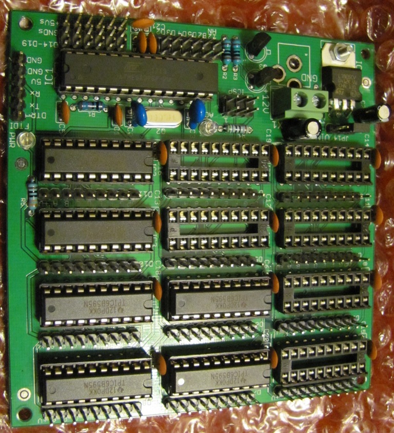
I even offer a board with a '328P and 1 to 12 shift registers to control up to 96 outputs. Cross Roads Electronics
That is great idea. Im just asking to confirm. TPICB595 does not source they sink right ? then I need to change my design by connecting anode to its drain pins. My solution is this , I will connect jumper to the anode and cathode of the leds, if 74hc595 does not work like this time, I will remove the jumpers from ground side and connect them to kathode side. This way I will have 2 shift register on board for fail safe. I just want to as what is the value of ceramic capacitors in your circuit ? I did not use any ceramic capacitors in mine. Is is better for high frequency operations ?
CrossRoads:
Well, 80mA is greater than 70mA. As an engineer I would suggest something else. And did, if your load can work with the shift register sinking current from it to activate it. LEDs and motors work great that way.
I even offer a board with a '328P and 1 to 12 shift registers to control up to 96 outputs. Cross Roads Electronics
It later occured to me, if the problem caused by shift register overload, it would be go away when i changed the whole shift registers right ? im not opening all of tbe outputs at all times. It consumes max 50 ma at a time. I have disassemled the fried pcbs. There is no visual problem other than fried power rail. I will post pics after I shop some components today.