hello there.
it's long that i've done anything with an arduino so probably you could consider me a newbie —
i'd appreciate any help very much.
i have an old simmons drummachine which uses audio(jack-)inputs to trigger its (5) sounds.
each sound (bd, sn, tom1...) has one input. the basic idea is to connect drum-pads to these triggers.
what i am trying to do appears to be most basic but i absolutely cant get it to work:
i need 5 pins to individually output a tone / noise / sound depending on which midi-note is input via a midi plug.
the quality or style of this sound is quite irrelevant for now; the simmons is rather forgiving as for it's trigger signals.
i got the midi-in part quite done; my main problem is to get the sound-part working — and what appears to be an even bigger problem
is to make sound "come out of" 2 (or more) pins at the same time.
please help me — i've been going mad over this for the past days! :0
Can you supply more info as to the inputs?
What signals does it require and at what level?
When you say "output audio at the same time", I assume that the unit has multiple connections on the jack, is that right?
As to triggering more than one sound at a time, is the unit capable of this, i.e. not monophonic?
hello,
thanks for your quick reply! i'd be gracious if you could help me out
judging by the manual i found online, the following specifications are needed as for input:
Can you supply more info as to the inputs? What signals does it require and at what level?
the trigger input is a 1/4 inch phone jack which seems to use an audio signal in the range on 5mV - 1.5V
(i dont know if / how that can be translated into input volume. for now i've been testing the input with 2.5V and it
appeared to work ok. i think a weaker audio signal could work better)
When you say "output audio at the same time", I assume that the unit has multiple connections on the jack, is that right?
the device has 5 "sound-generators", each dedicated to one drum (bd, snare, hh, tom1, tom2.. something like that). each of these has an own 1/4 inch input that triggers it.
As to triggering more than one sound at a time, is the unit capable of this, i.e. not monophonic?
yes, the device is polyphonic. the resulting "sound" can be output via a stereo. because the device is polyphonic, i also need to be able to trigger more than one drum at the same time.
this may be useful:
besides the 5 (audio-)trigger-ins (1/4 inch phone, as mentioned) the simmons also has a 8-pin DIN input. i have figured out, that 5 of its pins are dedicated to the indivdual drums. judging the the specifications above, this input needs to be in a range of 1V - 15V. it'd be an ideal scenario (best-case :)) to use this input rather than the "audio-"trigger inputs, because i suppose i'd then only need to run one cable to the device.. but anyhow, any method is very appreciated.
oh, and on the side. in case this is handy to know:
when i tried triggering the pins (of the 8-din connector) i simply used the audio-signal (maybe a no-go?) which had ~2.5V.
this worked, but the triggered drums were very silent. i suppose applying more voltage to the pins would make the drums louder — although i'm not sure and there's no information on this DIN input anywhere.
Let's first try your preferred method of using the 8 pin connector.
I have attached a schematic for you to test with before proceeding.
Please note that with the test circuit, I have assumed that on the 8 pin connector, each drum triggers voltage is positive and that there is a common ground for all the triggers.
Please confirm this before you proceed.
If the attached circuit works, then it will be a simple matter to use the Arduino to control the drums by using digitalWrite.
i have a suspicion which pin of the din is used for ground. anyhow, is there a way / need to test this beforehand?
It could well be that each of the trigger pins could be for grounding, I don't know, you will have to check that.
What you could do is first look for a common ground on one of those 8 pins, then use something like a 1K resistor and quickly connect the resistor between what you think is the common ground and one of the drums triggers and see if you get sound out.
If you do (even if it's low), then you know that you are on the right track and can always tweak the resistor value.
If it turns out that it does indeed work, it will also be pretty easy to interface to the Arduinos pins.
Glad it's working.
Now you try it with your Arduino.
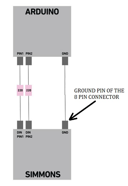
Connect a series 220 ohm resistor between the Arduino and the trigger input, then using digitalWrite, make that pin go high, wait a bit and make it go low again.
Don't forget to join the common gnd of the drum machine (on the 8 pin connector) to that of the Arduino's board.
ok .. i'm really slow and clueless.. can you help me out?
is this sketch total rubbish or am i going to do it right?
and further more:
i suppose the volume of the triggered sound is so decent because of it being triggered by 9V.
arduino via USB is only 5V, for my understanding.
would this mean, if i later run the arduino on a 9V power supply (battery or adapter), that it should work aswell?
You don't need the 1K resistors anymore, the two 1K resistors were just to divide the 9V battery voltage by two (to 4.5V) which is very close to the Arduinos 5V.
The reason why I recommended using the battery and not your Arduino for the test, is that it's safer (for your Arduino) and also quicker as you didn't have to write any code.
So to recap, you only need one 220 ohm series resistor for each trigger and to connect the grounds.
The 220 ohm resistors are to protect your Arduinos pins against excess current in case of a short.
and to still not stop bugging you (and before i run off to the supply store):
is there a (simple) way to later link the voltage (supplied by each of the arduino pins) to the velocity of the incoming midi note?
the midi-part i think i could manage, but i have no clue as for the electrical part. i would suppose by simply lowering the voltage i send to the DIN pins, the triggered sound should lower in volume. is there anything like a "digital" resistor i could set with the arduino (between arduino PIN and DIN PIN)?
if this means to much effort, don't bother. or tell me which parts to get and i'll fiddle around with it.
Using PWM is do-able with a low pass filter.
You could also read midi messages coming into the Arduino, then extract channel number, duration and so on then use digitalWrite to control the triggers.
What I know about music creation is just slightly more than zero, but there are loads of midi examples on the forum.
If you want to lower the volume by means of a resistor then have a look at voltage dividers like the one I used for the initial test.
You may have to mess about with the values to get the correct ones.
Alternatively, "digital pots" could work.