Stepper motor stops, presses limit switch

Hello, all..

I have the task of making a tool using stepper motor, LDR sensor, and 2 limit switch ..

The way it works is if the LDR sensor gets the light then the stepper motor to the right, if it is dark then the stepper will go to the left ..

Now the stepper motor code has been successfully moved according to the command from the LDR sensor to the right, how to stop stepper motor when pressing limit switch (1)? And rewind to the left when the light is dark, then stop when pressing limit switch (2)?

Code problem only in stepper motor and limit switch ...
Please help

#include <LiquidCrystal.h>

int ldr = A1; 
int light = 0;
int limit_switch_a = 6;
int limit_switch_a = 7;
int IN1=8;
int IN2=9;
int IN3=10;
int IN4=11;
int count=0;
int delayTime = 3;
int delayTime1 = 3;

LiquidCrystal lcd (13, 12, 5, 4, 3, 2);

void setup() {
Serial.begin(9600);
lcd.begin(16,2);
pinMode(IN1,OUTPUT);
pinMode(IN2,OUTPUT);
pinMode(IN3,OUTPUT);
pinMode(IN4,OUTPUT);
}

void loop() { 
light = analogRead(ldr);

 if(light < 300 ){
 lcd.print("NIGHT");
 left(5,delayTime);
 }
 else if(light < 1000){
 lcd.print("AFTERNOON");
 right(5,delayTime);
 }
 delay(delayTime);
}

void right(int stepps, int delayTime){
    
  for (count = 0; count < stepps; count++)
  {                                                                                                                                                                                                                                                                                                                                                                                                                                     
        //step a
        digitalWrite(IN1, HIGH);       
        digitalWrite(IN2, LOW);        
        digitalWrite(IN3, LOW);        
        digitalWrite(IN4, LOW);        
        delay(delayTime1);
        //step b        
        digitalWrite(IN1, LOW);
        digitalWrite(IN2, HIGH);
        digitalWrite(IN3, LOW);
        digitalWrite(IN4, LOW);
        delay(delayTime1);
        //step c
        digitalWrite(IN1, LOW);
        digitalWrite(IN2, LOW);
        digitalWrite(IN3, HIGH);
        digitalWrite(IN4, LOW);
        delay(delayTime1); 
         //step d
        digitalWrite(IN1, LOW);
        digitalWrite(IN2, LOW);
        digitalWrite(IN3, LOW);
        digitalWrite(IN4, HIGH); 
        delay(delayTime1); 

   }  //End For 
}

void left(int stepps, int delayTime){
  
   for (count = 0; count < stepps; count++) 
  {  
        digitalWrite(IN1, LOW);
        digitalWrite(IN2, LOW);
        digitalWrite(IN3, LOW);
        digitalWrite(IN4, HIGH); 
        delay(delayTime1); 
        //step c
        digitalWrite(IN1, LOW);
        digitalWrite(IN2, LOW);
        digitalWrite(IN3, HIGH);
        digitalWrite(IN4, LOW);
        delay(delayTime1);        
        //step b        
        digitalWrite(IN1, LOW);
        digitalWrite(IN2, HIGH);
        digitalWrite(IN3, LOW);
        digitalWrite(IN4, LOW);
        delay(delayTime1);            
        //step a
        digitalWrite(IN1, HIGH);
        digitalWrite(IN2, LOW);
        digitalWrite(IN3, LOW);
        digitalWrite(IN4, LOW);      
        delay(delayTime1);   
  }
}
Fix your compilation error - looks like a copy & paste error left you with two declarations of limit_switch_a.

Set the pinmode on those limit switches; preferably to input_pullup.

digitalRead the appropriate input in the for loops in Left and Right functions to see whether you should stop stepping. Don't forget that the pullups mean that LOW represents a pressed limit switch.

Get rid of delayTime1 or stop passing an unused delay to the stepping functions.

2 variables both called limit_switch_a mean that doesn't even compile.

Functions left() and right() take input parameters that they never use.

And I can't see any attempt to make any use of any limit switches. How are they wired, what do you expect to see when they are pressed/not pressed and when are you planning to check them?

Steve

Hi,

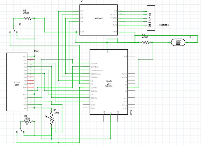
Can you please post a copy of your circuit, in CAD or a picture of a hand drawn circuit in jpg, png?

We need to see how you have connected your components.

Please not a Fritzy picture.......

Thanks.. Tom... :slight_smile:

Oh yes I am giving the limit switch declaration, which is correct
Limit_switch_a = 6;
Limit_switch_b = 7;

Yes indeed i have not given the complete declaration in the code, because i do not know the correct code at the time of entering the code void setup and so on to the void loop, like input_pullup it's the right code how.
Please help me just confused stepper motor stop when pressing limit switch a and limit switch b.

To sketch and draw the circuit please look under tom :slight_smile:

Hi,
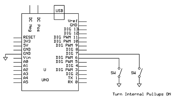
Thanks for the diagrams, your limit switches need to wired differently to what you have.


Your wiring should be like this, with pullups turned ON in your code.


Tom.... :slight_smile:

Hi,
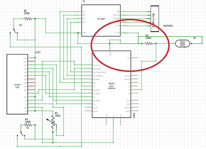
I think you might be better to draw your circuit with pen and paper.
Circled area looks very wrong.

Tom... :slight_smile:

Okay thanks, but in the scheme it is the result of that color image, i am also confused kok vcc line connect to ground, but i understand if it is wrong, but in my practice tool is correct maybe my schematic is wrong draw it.
Which is the question is please help how the code if the limit switch is pullup, the code that I put it stepper can rotate with data from LDR sensor, only the limit switch code makes me so stressed :slight_smile:

Sorry out of the theme, yesterday I did a limit switch experiments with LEDs that the limit location of the switch with the arduino was correct with the input_pullup code.
Only stepper motor code with limit switch I still can not understand.
This example of his code led-limit switch

int led = A2;
int LS1 = 6;
int LSstate=0;

void setup() {
  // put your setup code here, to run once:
  pinMode(led,OUTPUT);
  pinMode(LS1,INPUT_PULLUP);
  Serial.begin(9600);
}

void loop() {
  // put your main code here, to run repeatedly:
  LSstate = digitalRead(LS1);
  Serial.println(LSstate);

  if(LSstate==HIGH){
    digitalWrite(led,HIGH);
  }else {
    digitalWrite(led,LOW);
  }
}

please help me :slight_smile: