I have two rows of 4 RGB Led's. The anodes are powered with P-Fet's and go through the TLC5940. I looked at the sample library but it pretty much just confused me. I believe what is suppose to happen is that the Led's are suppose to but turned on and off very quickly so that your eyes cannot detect it and to minimize the amount of power it would take when all of them are on. Can someone point me at a link or just assist me on how I can control this small matrix with the TLC5940 multiplexed. I have searched and came across a few things but all of them are a lot more complex. I prefer to start simple and add up. Please let me know if you can assist me. Thank you in advance.
In his schematic you'd assumedly be skipping the switch and diode that he has associated with each LED, and also note that all of the R/G/B channels should be connected vertically.
Chagrin:
You've seen Grumpy Mike's example? Mini Monome
In his schematic you'd assumedly be skipping the switch and diode that he has associated with each LED, and also note that all of the R/G/B channels should be connected vertically.
I scaled it to 8X8 in my Hexome Hexome on Vimeo
With one TLC5940 per colour so that you can have separate current control allowing you to balance the colours.
The TLC5940 does not required LEDs to have current limiting resistors as there is a current limiting circuit in the chip. Just one resistor is needed to set the current for all the LEDs.
If I'm reading it correctly, your schematic shows 15k resistors connected to each diode. If I'm not using the diodes, I can eliminate the resistors as well then?
Yes those are pull down resistors for reading the switches. That circuit uses the same matrix scanning that lights the LEDs to scan for key depressions at the same time.
Grumpy_Mike:
Yes those are pull down resistors for reading the switches. That circuit uses the same matrix scanning that lights the LEDs to scan for key depressions at the same time.
Ah I see. And will a 60v 27a FET work okay in lieu of the one you suggest in your schematic?
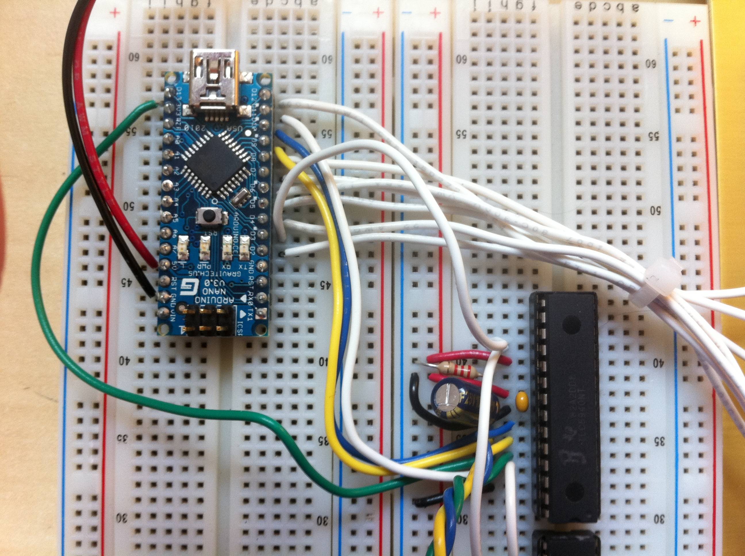
I've got everything hooked up, but was hoping someone could double-check my work before I blow something up.
In particular I'm worried about a few things:
I'm not sure I wired the decoupling capacitors correctly
Im not sure I wired the FETs correctly
I connected the 5940's together as per the playground article* which seems to differ slightly from Grumpy Mike's schematic †.
I used open digital pins to add in the extra rows of LEDs/fets. The pins in Grumpy Mikes schematic seemed pretty particular and some out of order so I'm worried I'm missing something here.
The Arduinome_4X4_RGB.pde fails to compile (error: 'PD6' was not declared in this scope)
Note: Ignore the IR LEDs and photoresistors since I don't have those hooked up yet. Also ignore the scribbles on the breadboard. They were there when I bought it from a scrap house and won't come off.
EDIT: Also, I know the LED's aren't connected to the 5940's yet, but will connect up by color (RGB) to the three chips.
The Arduinome_4X4_RGB.pde fails to compile (error: 'PD6' was not declared in this scope)
Looks like there has been a change in the latest Arduino distribution that makes this not compile. Take the TLC5940Multiplex_defines.h file and add the following to the end:-
I connected the 5940's together as per the playground article* which seems to differ slightly from Grumpy Mike's schematic
My schematic uses a modified early version of the TLC5940 library which is what I based my code on. The "official" library changed some of the pins, there pins have fixed hardware functions so it is not a simple matter to change them. So you must use my wiring with my code or the other wiring with the other code, you can't mix them.
I'm getting very close! The code complied and some of the LED's are firing, but are very weak. I think it's because there's not enough power. The schematic calls for +5v on pin 19, pin 21 and the FETs. I noticed the schematic says "+5v DC Prog" on pin 19. Does that mean I should be using a separate power supply there?
Grumpy_Mike:
No, that is the pin you put an extra high voltage on if you want to programme the grey scale correction rom.
It turns out I had read 4K7 as "47k". I replaced all the FET resistors with 4.7k and now the brightness is good.
When I power it up or run any of the Processing examples individual rows are different colors, but not individual LED's. To reduce complexity I removed the other two 5940's and reduced the matrix to 4x4, figuring I'll scale it once I get the basics working. Any ideas?
Grumpy_Mike:
You need to post a schematic not a photo of a jumble of wires.
Sorry, I'm trying to follow your schematic exactly, but was only able to get whole rows to light up. I'm really new to reading schematics and think I might have messed something up which is why I posted the pics. I've been tying to get it going all day, but I must be missing something.
Is there anything else I can do to make troubleshooting any easier?
I've created a Fritzing file which mirrors my breadboard setup at the moment. I've left out the RGB cathode wires for better readability. I hope this helps. I really appreciate all of your help getting me this far!


