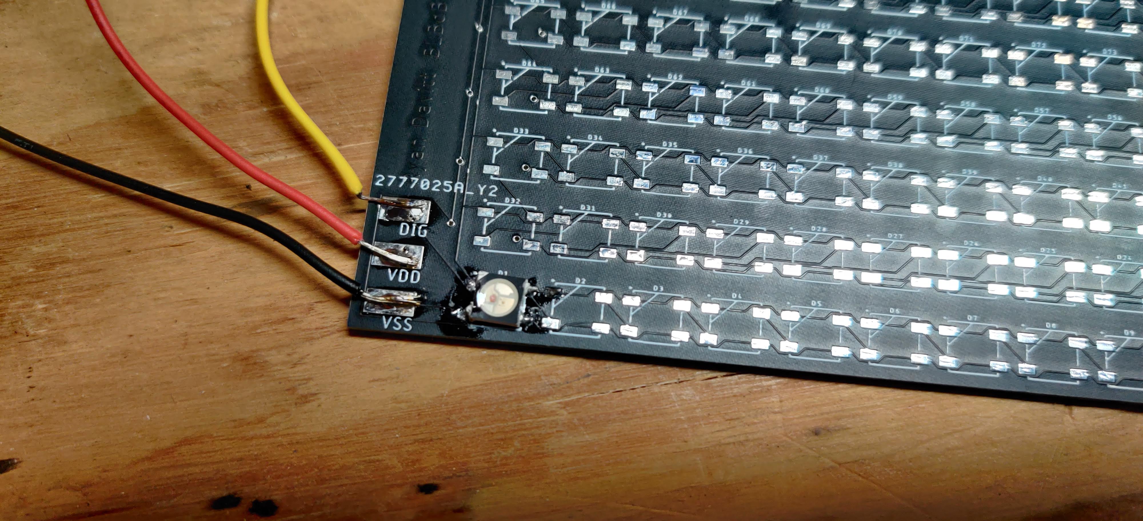
Hi all! I'm working on a small project that is a 16 by 16 array of LEDs on a custom PCB. I've soldered in the connections and the first WB2812B, but no dice: it just won't light. I've tested all connections with the continuity setting on my multimeter (both from the Mega2560 to the board and the board to the LED) with positive results, and have triple checked my rather simple code (pasted below), which appears to be working (the builtin LED on the Arduino flashes as it should, showing that the code is looping without problems). I'm a bit rusty at coding for FastLED, so my mistake might very well lie in the code, but I can't figure it. I've worked on this for about four hours straight to no avail. Any expert advice? Thanks!
#include <FastLED.h>
#define NUM_LEDS 4
#define DATA_PIN 6

CRGB leds[NUM_LEDS];

void setup() {
  // put your setup code here, to run once:
  FastLED.addLeds<WS2812B, DATA_PIN>(leds, NUM_LEDS);
  pinMode(23, OUTPUT);
  pinMode(LED_BUILTIN, OUTPUT);
}

void loop() {
  // put your main code here, to run repeatedly:
  digitalWrite(LED_BUILTIN, HIGH);
  leds[0] = CRGB::Red;
  FastLED.show();
  delay(100);
  digitalWrite(LED_BUILTIN, LOW);
  delay(100);
}
No clue what a decoupling capacitor is... Sorry, novice electronics hobbyist at work here. And I'm pretty sure I've soldered them the right way around.
larryd:
One pixel will work without the capacitor.
In fact some WS2812B strips from China are being sold with only one capacitor per 10 pixels (not recommended!).
If your traces are connected properly, this one pixel should work.
BTW, your traces really should be wider > 30mil. You should have used VSS and VCC planes.
Okay, thank you. So then, the issue is that a single pixel isn't working without a capacitor, and I'd like to get at least one pixel working before I completely redesign and repurchase another batch of PCB. Other than maybe the trace width being the issue (which I'm not sure if it would or wouldn't have an affect), is there anything else that might be hindering the LED from working? Like, the decoupling capacitor maybe? (Wild guess, still not 100% sure on the total functionality of the decoupling capacitor, I'll keep Googling)
Ran to Fry's, grabbed some 0.1 uf Tantalum Capacitors rated for 35 Volts, and hooked it up as a decoupling capacitor (I think). Still no luck. I've checked continuity with my voltmeter thru my wires, thru my board, and thru the digital pin, all showing positive for continuity.
Any other glaring issues?
As Larry has said, the lack of the capacitor is not the cause of complete failure to work, but it is specified and indeed as is so often pointed out on this forum, a bypass capacitor is specified for every IC used - and these LEDs are of course, just that - ICs. (I first typed "logic IC" but that is in itself, misleading as the requirement is no less critical for analog ICs!)
I suppose two things remain: I am not familiar with FastLED, but Larry has verified your code.
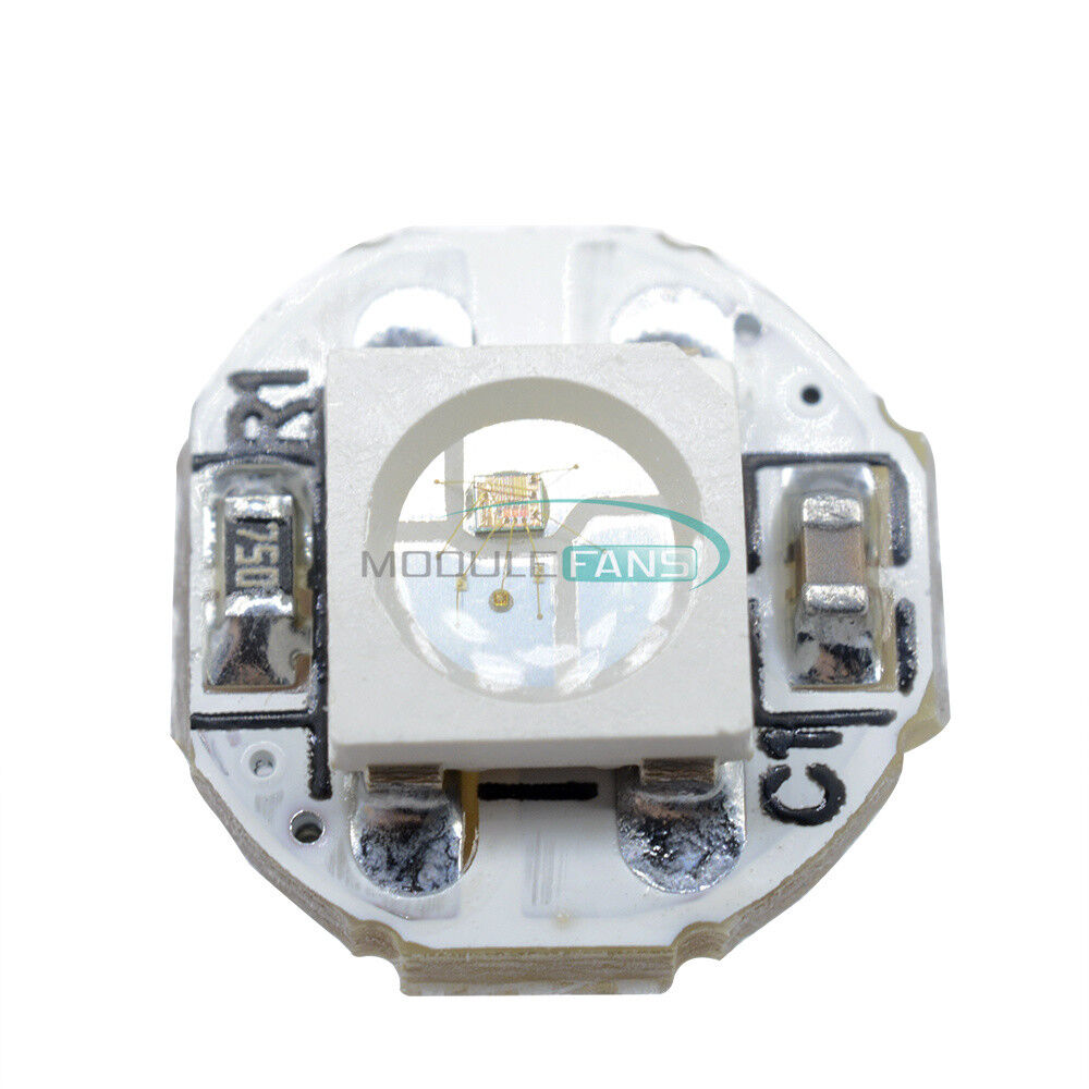
OK, just disconnect the wires from the PCB and carefully connect them to the correct pins on one Pixel.
Your PCB is in any case completely useless for the lack of the 0.1 µF chip ceramic capacitor for each chip and the wrong power traces.
Paul__B:
As Larry has said, the lack of the capacitor is not the cause of complete failure to work, but it is specified and indeed as is so often pointed out on this forum, a bypass capacitor is specified for every IC used - and these LEDs are of course, just that - ICs. (I first typed "logic IC" but that is in itself, misleading as the requirement is no less critical for analog ICs!)
I suppose two things remain: I am not familiar with FastLED, but Larry has verified your code.
OK, just disconnect the wires from the PCB and carefully connect them to the correct pins on one Pixel.
Your PCB is in any case completely useless for the lack of the 0.1 µF chip ceramic capacitor for each chip and the wrong power traces.
Connected the wires direct to the pixel, but to no avail. I'm currently reschemticing (let's assume that's a word) the board to include 0.1uf SMD capacitors. Thank you guys for your help so far. Hopefully we can figure out what is wrong.
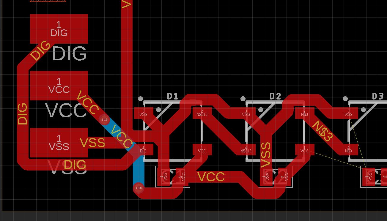
Okay, so, I know I'm asking a lot, but if anyone can double check my work here, am I connecting C1 and C2 (the 0.1uf SMD caps) correctly for D1 and D2 (the WB2812Bs)? I apologize for overstepping my help if I am, but I'd really like to not wait another month for another batch of PCB to ship in from China, only to find out it still doesn't work.