Controlling 4pin fan with PWM 25Khz

Hello, first of all thanks for reading this post. I'm completely stuck on a project. I am currently doing my first project with my first microcontroller.
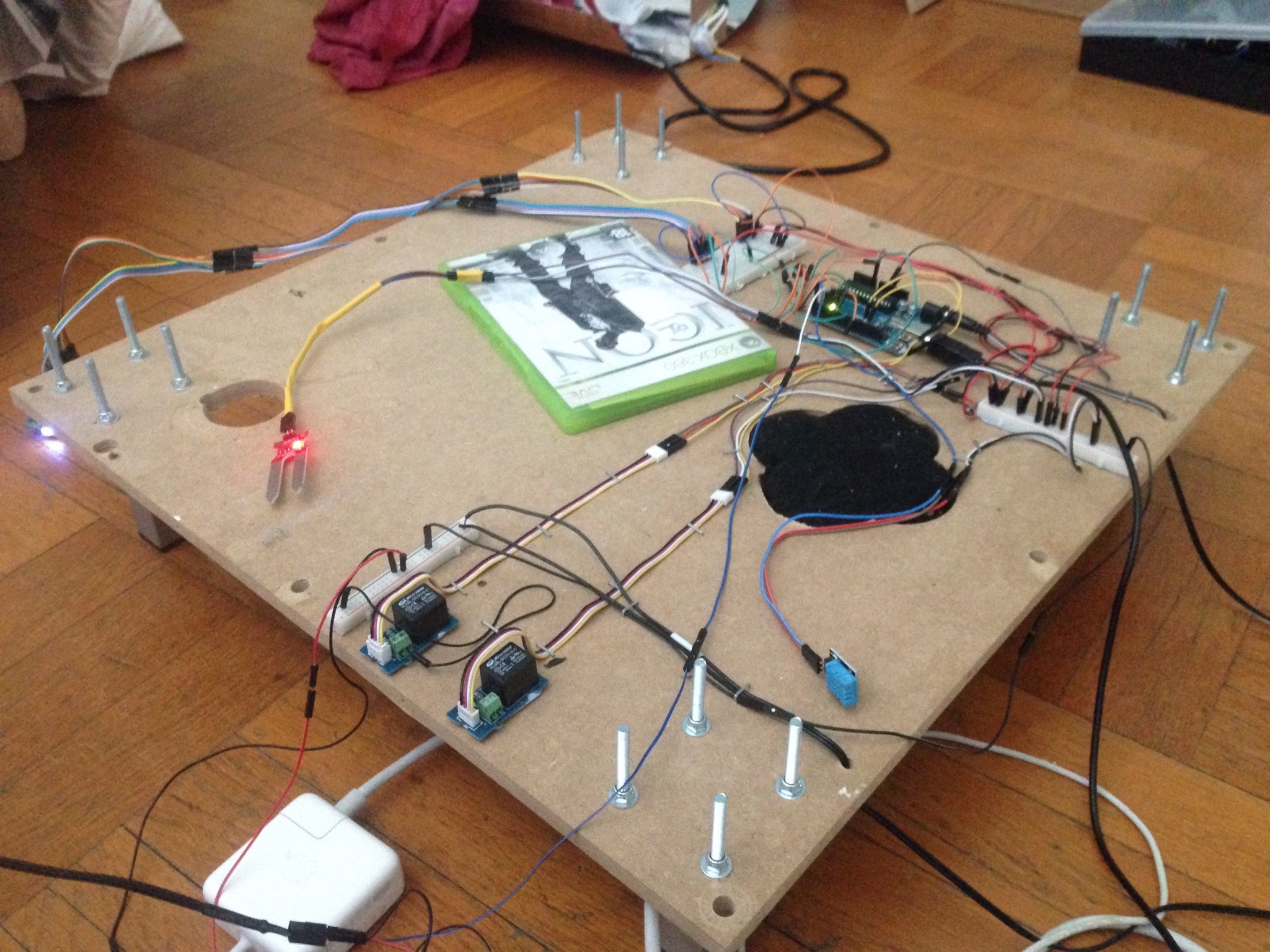
I'm making a culture chamber with a CFL bulb, 2 relays, a DHT11 (a temperature sensor), a moisture sensor and so far everything was doing well. (i'll post the code for the entire project if needed, but it's a bit long)
However, if most of it worked i couldn't manage to set the Fan I used at the speed i wanted, with any code it would run full speed.

The Fan is a Cooler Master A14025-20RB-4CP-F1.
It functions on 12v 0,8A.
And is powered by an adaptor (the ground is connected to the adaptor and to the arduino)

  • on -
    +12v on red
    and signal plugged correctly

When i plug the adaptor The fan runs at full speed.
I wrote this code to see if i could Set the fan's speed;

 int VentPin=3;
void setup() {

pinMode(VentPin, OUTPUT);
}

void loop() {
  analogWrite(VentPin, 60);

  delay(5000);
  
  analogWrite(VentPin, 60);

  delay (5000);

  analogWrite(VentPin, 255);
  

}

But the Fan just kept going 100%. So I've found that the PWM of my Arduino Uno wasn't in 25KhZ which was the frequency of my PWM's fan. (can't say if i've said in properly haha)

I Used this new code using a PWM library:

Library can be found here:
http://forum.arduino.cc/index.php?topic=117425.0
on this link:
https://code.google.com/archive/p/arduino-pwm-frequency-library/downloads

And Here's the code:

#include <PWM.h>

//use pin 11 on the Mega instead, otherwise there is a frequency cap at 31 Hz
int led = 7;                // the pin that the LED is attached to
        // how many points to fade the LED by
int32_t frequency = 25000; //frequency (in Hz)

void setup()
{
  //initialize all timers except for 0, to save time keeping functions
  InitTimersSafe(); 

  //sets the frequency for the specified pin
  bool success = SetPinFrequencySafe(led, frequency);
  
  //if the pin frequency was set successfully, pin 13 turn on
  if(success) {
    pinMode(13, OUTPUT);
    digitalWrite(13, HIGH);    
  }
}

void loop()
{
  //use this functions instead of analogWrite on 'initialized' pins
  pwmWrite(led, 0);
  
  delay(5000); 
   
  pwmWrite(led, 120);
   
  delay(5000);
      
  pwmWrite(led, 255);
}

And nothing happened, and now i read few posts saying that 25Khz is impossible with an arduino since the base frequencies divided by 2,4,8 etc... don't match with 25Khz.

Can I set the speed of the fan with my arduino ? Or Maybe i have made a mistake i can't see..
thank you for your time.

Did you connect the grounds?

Yes, 25kHz PWM is possible ...

word VentPin = 3;

void setup() {
  pinMode(VentPin, OUTPUT);
  pwm25kHzBegin();
}

void loop() {
  pwmDuty(19); // 25% (range = 0-79 = 1.25-100%)
  delay(5000);
  pwmDuty(39); // 50% (range = 0-79 = 1.25-100%)
  delay (5000);
  pwmDuty(59); // 75% (range = 0-79 = 1.25-100%)
  delay (5000);
}

void pwm25kHzBegin() {
  TCCR2A = 0;                               // TC2 Control Register A
  TCCR2B = 0;                               // TC2 Control Register B
  TIMSK2 = 0;                               // TC2 Interrupt Mask Register
  TIFR2 = 0;                                // TC2 Interrupt Flag Register
  TCCR2A |= (1 << COM2B1) | (1 << WGM21) | (1 << WGM20);  // OC2B cleared/set on match when up/down counting, fast PWM
  TCCR2B |= (1 << WGM22) | (1 << CS21);     // prescaler 8
  OCR2A = 79;                               // TOP overflow value (Hz)
  OCR2B = 0;
}

void pwmDuty(byte ocrb) {
  OCR2B = ocrb;                             // PWM Width (duty)
}

Hello again, yes the ground is connected both to the arduino and the adaptor.
And i tried the code you just posted dlloyd. It doesn't seem to have any effect, the fan just keep going full speed. And any code i write doesn't seem to do anything....
Is this possible that my fan is damaged, something else is going on ? With the program on my arduino, i can even unplug the PWM of my fan and absolutely nothing happens...

Update: Hello everyone and thank for you patience. Turns out that the code dlloyd wrote works perfectly and it seems that i made a wiring mistake. So if you have the same issue verify twice your wiring haha:
PS: this is the wiring of my first project, i'm sure you'll understand why i made a mistake in this mess !
Thank you everybody ! And special thanks dlloyd you made a code that will be very useful for me :slight_smile:

dlloyd it is possibile to control more than 1 fan by arduino uno or mega with your code?

Dual 25kHz PWM using Timer1 ...

//Dual 25kHz PWM using Timer1 Mode 10

word pwmA = 160; // 50% duty (0-320 = 0-100% duty cycle)
word pwmB = 288; // 90% duty (0-320 = 0-100% duty cycle)

void setup() {
  pinMode(9, OUTPUT);  //pwmA
  pinMode(10, OUTPUT); //pwmB

  TCCR1A = 0;            //clear timer registers
  TCCR1B = 0;
  TCNT1 = 0;

  TCCR1B |= _BV(CS10);   //no prescaler
  ICR1 = 320;            //PWM mode counts up 320 then down 320 counts (25kHz)

  OCR1A = pwmA;          //0-320 = 0-100% duty cycle
  TCCR1A |= _BV(COM1A1); //output A clear rising/set falling

  OCR1B = pwmB;          //0-320 = 0-100% duty cycle
  TCCR1A |= _BV(COM1B1); //output B clear rising/set falling

  TCCR1B |= _BV(WGM13);  //PWM mode with ICR1 Mode 10
  TCCR1A |= _BV(WGM11);  //WGM13:WGM10 set 1010
}

void loop() {}

Thanks for inspirations :slight_smile: What about other UNO timers ? Can I use Timer1 and Timer2 together to control 4 fans or 3 timers to control 6 fans ? Something like that:

word pwmA = 160; // 50% duty (0-320 = 0-100% duty cycle)
word pwmB = 32; // 10% duty (0-320 = 0-100% duty cycle)
word pwmC = 64; // 20% duty (0-320 = 0-100% duty cycle)
word pwmD = 128; // 40% duty (0-320 = 0-100% duty cycle)

void setup() {
  pinMode(9, OUTPUT);  //pwmA
  pinMode(10, OUTPUT); //pwmB
  pinMode(3, OUTPUT);  //pwmC
  pinMode(11, OUTPUT); //pwmD

  TCCR1A = 0;            //clear timer registers
  TCCR1B = 0;
  TCNT1 = 0;

  TCCR1B |= _BV(CS10);   //no prescaler
  ICR1 = 320;            //PWM mode counts up 320 then down 320 counts (25kHz)
 

  OCR1A = pwmA;          //0-320 = 0-100% duty cycle
  TCCR1A |= _BV(COM1A1); //output A clear rising/set falling

  OCR1B = pwmB;          //0-320 = 0-100% duty cycle
  TCCR1A |= _BV(COM1B1); //output B clear rising/set falling

  TCCR1B |= _BV(WGM13);  //PWM mode with ICR1 Mode 10
  TCCR1A |= _BV(WGM11);  //WGM13:WGM10 set 1010

  TCCR2A = 0;            //clear timer registers
  TCCR2B = 0;
  TCNT2 = 0;

  TCCR2B |= _BV(CS10);   //no prescaler
   ICR2 = 320;            //PWM mode counts up 320 then down 320 counts (25kHz)

 
  OCR2A = pwmC;          //0-320 = 0-100% duty cycle
  TCCR2A |= _BV(COM1A1); //output A clear rising/set falling

  OCR2B = pwmD;          //0-320 = 0-100% duty cycle
  TCCR2A |= _BV(COM1B1); //output B clear rising/set falling

  TCCR2B |= _BV(WGM13);  //PWM mode with ICR1 Mode 10
  TCCR2A |= _BV(WGM11);  //WGM13:WGM10 set 1010
}

void loop() {}

There's only one ICR register unfortunately, so the other Timers are less flexible than Timer1.

:frowning: so, no chance to control more than 2 pwm fan by arduino uno/mega?

On an Uno:

With timer2, could get dual pwm at 31.37kHz using Mode 1. Using Mode 5 only get one pwm at 25kHz.

So, using timer 1 and timer 2, could get 4 pwm, 2 at 25kHz and 2 at 31.37kHz.

or 3 pwm at 25kHz.

Hi there,

I was wondering how would you actually use dlloyd's code to control the PWM? Wouldn't you need something like digitalWrite() somewhere in there to tell the Arduino to have a certain PWM value?

dlloyd:
Yes, 25kHz PWM is possible ...

word VentPin = 3;

void setup() {
 pinMode(VentPin, OUTPUT);
 pwm25kHzBegin();
}

void loop() {
 pwmDuty(19); // 25% (range = 0-79 = 1.25-100%)
 delay(5000);
 pwmDuty(39); // 50% (range = 0-79 = 1.25-100%)
 delay (5000);
 pwmDuty(59); // 75% (range = 0-79 = 1.25-100%)
 delay (5000);
}

void pwm25kHzBegin() {
 TCCR2A = 0;                               // TC2 Control Register A
 TCCR2B = 0;                               // TC2 Control Register B
 TIMSK2 = 0;                               // TC2 Interrupt Mask Register
 TIFR2 = 0;                                // TC2 Interrupt Flag Register
 TCCR2A |= (1 << COM2B1) | (1 << WGM21) | (1 << WGM20);  // OC2B cleared/set on match when up/down counting, fast PWM
 TCCR2B |= (1 << WGM22) | (1 << CS21);     // prescaler 8
 OCR2A = 79;                               // TOP overflow value (Hz)
 OCR2B = 0;
}

void pwmDuty(byte ocrb) {
 OCR2B = ocrb;                             // PWM Width (duty)
}

Thanks!

No.

This is unfortunately not the "usual" Arduino code. In this case you write to a register, specifically "OCR2B" with a byte, after configuring a number of related registers, as seen in the "pwm25kHzBegin" subroutine. For the code dlloyd provided, the subroutine "pwmDuty" does the job. "pwm25kHzBegin" configures Timer2 to run at the speed necessary to do this, in this case 2 MHz (the Arduino's 16 MHz clock divided by 8), and has it reset to 0 when it hits 80, so it "cycles" at 25 KHz, with each cycle divided into 80 "ticks". Because it's only divided into 80 "ticks" of the timer, the value can only vary from 0 to 79, so you get a PWM with each step at (100/80 = ) 1.25%. It also never fully turns off the PWM output (the lowest output is a duty cycle of 1.25% on).

If you want to better understand these registers, you'll need to read the docs on the Atmel microprocessor that's on the Arduino, the ATMega 328P (or 168 depending on how old your Arduino is). See here: ATmega328P

This works very well for an application that I'm building, but...how is it that I can't use another pin assignment (pin 5, for example) just by changing the VentPin declaration? I've tried it and there's no PWM output on that pin showing on the scope; is this coupled to the timer routine in a way I'm not seeing?

dlloyd:
Yes, 25kHz PWM is possible ...

word VentPin = 3;

void setup() {
  pinMode(VentPin, OUTPUT);
  pwm25kHzBegin();
}

.
.
.

For anyone reading this thread,.. I to was trying to get PWM control on pin 2 of a mega,.. and failing miserably,... as this code does not work on a mega 2560,.. however, I found a solution by using the 'timerthree.h' library.

diyhouse:
For anyone reading this thread,.. I to was trying to get PWM control on pin 2 of a mega,.. and failing miserably,... as this code does not work on a mega 2560,.. however, I found a solution by using the 'timerthree.h' library.

I was having the exact same problem till I found that timers on mega use different pins.
timer 0 (pin 13, 4)
timer 1 (pin 12, 11)
timer 2 (pin 10, 9)
timer 3 (pin 5, 3, 2)
timer 4 (pin 8, 7, 6)
As you can see with timerthree library you can pwm only 5, 3, 2 pins

Could use single 25khz pwm code provided by @dlloyd on other pin than D3 uno board?
Cause it used by interrupt for rotary encoder.
Thanks

For PWM you need control over frequency and duty cycle. @dlloyd is using timer2 which is attached to 2 pins, 3 (OC2B) and 11 (OC2A). These are the pins switched by the Output Compare interrupt. You could use either if you can set the frequency by simply using the clock prescaler. For timer2 you can divide by 1, 8, 32, 64, 128, 256 or 1024 and then 256 which is the full scale 8-bit run to overflow. With a prescaler of 1, this corresponds to a PWM frequency of 62.5kHz or 7.8125 kHz with a prescaler of 8. If one of those freqs is okay, then you can use OCR2A (for pin 11) and OCR2B (for pin 3) to control duty cycle, otherwise, you need to use OCR2A to set TOP for the counter to alter the freq leaving only pin 3 for duty cycle.

Easier I think to change the encoder to another pin. Lots of pin change interrupts available.

PEDANT alert! The above calculations are for fast PWM. For phase-correct PWM divide by 2.

Thank for clarification,good news i have found some delta fan on the basement,support Wide PWM Frequency Range Input (30Hz- 30kHz).

I think that i can use any pwm pin available.