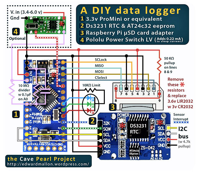
It seems like most on of the folks on this list already know more than I do about building data loggers, so please forgive me if this amounts to spamming the thread. But I wanted to post a link to a really inexpensive data logger I have come up with for one of my projects, based on a 3.3v Pro Mini and a cheap DS3231 breakout board from eBay.
I have put a few of these together now, and they all seem to be running well, with the only caveat being that the voltage regulator on the pro mini draws about 1.5mA* while the unit is sleeping. So not great for long term deployments, but good enough for the bench-top prototypes I have used them for thus far. Also, all the usual caveats apply regarding the reliability (drift, etc) of those knock-off RTC's. Rest assured that I use more reliable clocks for actual fieldwork. Still, you can put one of these things together for about $10-$20 depending on how cheap you want to go on the parts, and that's handy when you are just trying out a new sensor.
*Edit: Read through the thread: My current builds are usually around 0.35 mA. Without knowing it, I had bad SD cards drawing alot of current in the first few, and I did not pullup the unused lines (8&9) on the SD cards, which also caused some cards to draw more power because they did not go to sleep properly.
I know the new Pro Mini boards have a jumper that lets you disconnect the voltage regulator very easily. But I am using TinyDuinos for my long term deployments because although their mcu board is unregulated, they have regulators distributed to their shields, so the SD card, etc. still gets a steady 3.3v even though the Vbatt varies widely over time. Their physical profile is compact, and when bolted down is pretty resistant to knocking around, which for me is an issue.
But this little ProMini logger should still go at least a couple of months on 3x AA's and that's probably Ok for alot of people. I have also been looking at the Ultra's from Rocket Scream, as their voltage regulator has a much lower quiescent current than the sparkfun board. I will get around to testing them out eventually.
That reminds me about another question I have been meaning to post to the playground, regarding sleeping & data loggers
There are lots of code examples out there where people use the power.h library to shut down peripherals (SPI, TWI, etc) during sleep mode to save power, but I have yet to find an example that has devices connected to those peripherals both before and after the sleep cycle.
When I have both an SD card, and several sensors connected to the I2C lines (with ext 4.7k pullups) - what happens to those external devices?
Do those connected sensors get confused when the Arduino peripherals stop?
Do I then have to re-initialize them all again like I did in the setup after enabling I2C and SPI?
If so there might be no net power savings for shutting down the peripherals, because many of the sensors (and the Sandisk sd card) draw very little power when sleeping, but take a significant amount of time & power to initialize...
I would appreciate advice from anyone who has experience with this...
(..also wondering if shutting down a peripheral on the mcu, but having a real device connected to the wires, creates some kind of unexpected current drains, etc, pins floating? or something else like that?)
P.S. I was not planning to shut off the BOD...It seems like a handy thing to have on battery powered loggers.
I have about a weeks worth of burn test data in hand from six different loggers built with this basic design. As I expected, the pro mini (clone) boards draw down a 3xAA power supply at almost the same rate no matter what the sample frequency is set to, indicating that the sleep current on the MC5205 voltage regulator they use is the biggest load on the system. From these rough tests it looks like I should get at least 3-4 months of operation out of them (on regular alkalines - 1/3 more with lithium) before the power supply gets down to the 3.35v minimum needed by the regulator.
But the BIG news is the Rocket Scream Mini Ultra:
As I want to see how gracefully these voltage regulated systems behave when the batteries croak, I started this unit on a 3.4 volt power supply which already had a dead cell in it just to bring the voltage into the range of the voltage regulators minimum.
More than 40000 SD card records later and the voltage is now at 3.3volts. THIS THING HAS UNBELIEVABLY GOOD SLEEPING POWER CONSUMPTION FOR A VOLTAGE REGULATED BOARD. I did nothing special to the board myself, just loaded the same code running on the clone board tests above, which makes liberal use of generic sleep code (ie: not using Rocket screams special libraries!) I can only assume they shipped the units with everything, including the BOD fuse, turned off, because this thing is performing like one of my unregulated tiny-duino based systems.
I will leave this unit running until the voltage divider reading vRaw gets to 2800 mv, (yes, I know this might be a destructive test as this is below the regulators minimum input rating) I still want to see how gracefully it handles a full brown out, as it is pretty much inevitable that my loggers will face this trial sooner or later.
So if you are building a logger based on this design, and you can afford $15 for the Rocket Scream boards, you seriously extend the operating life of the logger because the sleep current is so good with those boards.
I just wanted to post an update on this thread, as I have built many more of these loggers, and learned quite alot while testing them. I have recently learned that the SD cards are overwhelmingly the most important part of the system when it comes to power consumption. A few good cards sleep below 0.25 mA right off the bat and others need you to pull up the unused lines (which I left unconnected and "floating" in the original design) before they will draw low sleep currents. There are oodles of fake cards out there, and I was unaware of the huge difference (up to 5mA!) they make to performance of this logger design. Without my knowing it the Rocket Ultra logger that I was raving about in the last post had the benefit of the "best" low current card I had on hand, even though on the surface all the cards looked like identical sandisk 128mb microSD cards.
So the rocket ultra is still the best board to use, but the delta is only about 0.06 mA for the sleep currents, between several different "mini" 3.3v boards due to the different regulators. My benchmark for a typical build is to have it sleeping at about 0.33 -0.35 mA ( with an ADXL345 attached and drawing about 40 uA) which should very comfortably get over a year on the 3 AA's I power them with.
I just wanted to post an update to the 3 component logger, which adds the Pololu Power Switch LV to the mix so that the system more gracefully handles powering down when the batteries go low.
Of course there is no free lunch, so the switch bumps the average current draw for one of these loggers (regulator always connected) to about 0.6 mA. This should still be good for a year of operation on 3x AA batteries, but I will be looking for a loss less latching relay as alternative to that switch later.
I have also included links to the parts if anyone wants to put one together, and there is a updated logger script on my Github that would be really easy to modify to whatever sensor you are trying to use. If you put header pins on the "innermost" pads of the Power switch, you can just fit the whole thing on a 1/2 size breadboard.
Have you thought about driving/powering the SD card from a digital output pin.
That way you could save your data in SRAM and only write to SD card say every hour or so.
So set all wires to SD card as input(low). And when you need to write to SD reconfigure power & signal lines to SD until the write is complete.
If the SD is the biggest draw, then it seems to make sense to control all the power going to it.
Depending on the amount of data required, you could even log to eprom and just dump the data to SD when full, taking note of the max lifetime write cycles to eprom.
Well (thanks to fat16lib) I now know that the sleeping SD cards are only responsible for around 0.06 mA of my sleep current if I have an authentic card that goes into a proper sleep mode. Powering with 3x AA's means that this is well within my >1 year of operation target.
Also I think there are issues around re-initializing the SD cards, both on the driver side which might not like calling a begin function several thousand times, and on the amount of time/power cards take to go through the init process. I have not done a detailed look at this yet, but if I go down to a 5 minute sample interval, it might actually draw more power to keep restarting the SD cards that often. Can you gang pins to power loads above the limit on each pin? The card specs goes up to 80-100 mA max currents, and things like the new file creation event (~once a month) are a sustained drain big enough to pull the voltage on the AA's down by a few tens of millivolts. So if I powered from the pins, they would take a real hit there.
Some of my sensors have similar start-up problems as they always seem to throw a few bad readings unless I give them enough settling time, so I have taken the approach to sleep, rather than de-power and wait for them to settle every time.
I currently buffer the data to the AT24C32 eeprom first, then dump to the SDcard, but as I use PString and ASCII encoding (saving me from buffer overflows when I make an error), I only get about 64 read cycles into the 4k eeprom before an SD write event. This did save a reasonable amount of power over just writing data to the cards at every read cycle, but not as much as I though it would, so eeproms don't seem to be that much better than SD cards, so far as my admittedly crude testing methods could determine:
I also though about trying to eliminate the SD cards entirely, but on the pragmatic side of things, downloading the data from eeprom only loggers is a significant irritant in the field. Especially if you have many units deployed in a cave system that need servicing. I want to just pop in, swap the batteries & sd cards, change the desiccant pack, and be back out. Sometimes it's a days work just to get out to the deployment site, and we have lost laptops while tethered & downloading because of bad weather (ie: torrential downpours). And finally, I would have to significantly improve my coding skills to get all the data from a long deployment stuffed into an eeprom and I just don't have the chops for that yet.
AnalysIR:
Have you thought about driving/powering the SD card from a digital output pin.
SD and microSD cards pull large currents way beyond an Arduino pins output,
and whenever powering a logic system you also have to consider the current
pulse needed to charge the decoupling capacitors, which means some sort
of switching-speed or current limit may be needed to prevent a dip in the supply
during switch-on. A p-channel MOSFET with relatively large gate resistor
is one way - the high value of gate resistance means a slow turn on to limit
the current into the switched module's decoupling capacitors. p-channel allows
high-side switching. Logic level of course, here 3.3V logic compatible,,,
BTW one solution for powering such 3.3V circuitry that is pretty neat is direct power
from a LiFePO4 cell. This lithium chemistry is nominally 3.2V and actually is
nicely within the 3.0 to 3.4V voltage range across the whole discharge cycle.
BTW one solution for powering such 3.3V circuitry that is pretty neat is direct power
from a LiFePO4 cell. This lithium chemistry is nominally 3.2V and actually is
nicely within the 3.0 to 3.4V voltage range across the whole discharge cycle.
I built a GPS logger using LiFePO4 cells, very energy efficient
Look here
I looked at other battery chemistry early on as part of my quest to save power by getting rid of the voltage regulators, but decided to stick with AA'a as part of an "off the shelf" design requirement for the entire project. It's very annoying to have to wait for a custom battery shipment in the field if TSA suddenly decides that you just can't fly with 20 XYZ batteries any more.
And for my flow sensor application, I have the side benefit that the extra ballast mass from 6 x AA batteries (almost 150 grams), helps to suppress noise caused by vortex shedding. Lithium based batteries have so much more power/weight, that I just end up having to throw in extra ballast weights to make up for it. So it comes out in the wash.
Recent testing shows that the MCP1700 regulator on the Rocket Ultra boards is only wasting about 0.012 mA when the units are in sleep mode. My original goal was to get 1-2 years of operation out of these loggers and with 3 AAs, I think I might get there even without the removal of the regulators.
I recently came up with a new underwater housing design that is very easy to construct from PVC with basic tools, so I thought I would post it to the Arduino forum in case other folks here were looking for such a thing. I also posted a DIY underwater connector system, and if you combine the two you would have a reasonable way to package batteries underwater for something like an ROV. The Formufit table leg caps that this design uses are available in different diameters.
The logger itself is a variant of the three component design that I posted earlier, but to fit it into the 2" pipe, I had to flip the RTC board over. In hindsight, I probably should have been doing this all along as it makes it easy to change the coin cell without having to undo any of the standoff bolts.
Please, the labelling of the six pins in the SD card adapter am using is quite different, there is no MOSI, MISO and SPCLK, just a bunch of things I dont understand. I need help
ojipen:
Please, the labelling of the six pins in the SD card adapter am using is quite different, there is no MOSI, MISO and SPCLK, just a bunch of things I dont understand. I need help
Please start a new thread. This is nothing to do with showing off your project. Also state what adapter you have and what labels you see (photo).
The SD card adapter I am currently using is a "microSD card adapter for Raspberry Pi" from Adafruit. But there are many other options available, and I provided links to several of them at the bottom of the post with the schematic at:
I have found that some boards conduct heat to the pads holding spring pins much faster than others, which means if you linger while soldering, and hear a "snap" then you probably need to start over with a new board. Also, I have sometimes have very fine solder hairs bridging the contacts, which prevents the sd card from working. So I inspect the springs, and the jumper wires on the back of raspberry pi card adapter very carefully before connecting to the Arduino. It's also really easy to get the connections switched around, so I always use different colored wires for each SPI line
Attached is the back side of the Adafruit adapter, next to my schematic. With the numbering I used:
1 = Chip Select
2 = Data in = MOSI
3 = GND
4 = VDD (supply voltage, not over 3.3v)
5 = SCLK
6 = GND
7 = Data out = MISO
8&9 are not used, but are pulled up to VDD with a resistor from 20-50K ohm because I found that some SD cards drew much more sleep current if those pins were left floating.
And apologies to the thread in general if the housing photos were out of place. In my head, the weather proof housing is a necessary part of building a datalogger. I was just happy to finally have one that could be made with so few fabrication steps.
Also the space limitations of the 2" pipe design lead me to put the components in a dramatically different physical configuration than the builds I posted about in 2014, and this taught me some lessons that are not in the schematic. For example, flipping the RTC board over makes it much easier to change the backup battery after the unit has been running for a while.
That last part is optional, but worth tackling once you have built a few as it can easily extend your operating life to a year or more on 3 AA batteries.