After a failed attempt using a WS2803d, I am trying to use a TI TLC5940NT to drive LED strips. I have succeeded in that I am able to drive the strip, however the brightness I can achieve on the strip is very low.
I tried a few random things, but I am an electronics neophyte, so I not sure what I am doing. The one thing I could guess was maybe I am only getting 5V from Vin on the arduino instead of the needed 12v? I noticed that that when the Gate of the mosfet is on 5V the strip is brighter than when it is on 3.3V, but when the strip is on 5V it seemed the same brightness as with Vin.
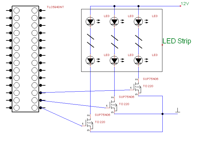
The way I had the mosfets wired was based on http://www.ti.com/lit/an/slva280/slva280.pdf which seemed to be basically what I was trying to do. I now have rewired them what I think is standard and I attached both an updated layout and an attempt at a schematic (only showing the mosfets/led strip etc). When I have it wired this way the LED strip does not turn on.
If I take the wire from the PWM on the TLC5940 to the gate of the mosfet and apply voltage (or touch it) the lights turn on. So the mosfet seems to work, it is just the PWM from the TLC5940 does not engate it? The PWM directly from the Arduino did engage the mosfet and the TLC5940 will run a LED just fine.
Hello, I'm trying to do similar setup with P16NF06 n-mosfets. And I'm stuck with led strip not lighting up. So mosfets are working just fine being connected to arduino pwm directly (like Usage | RGB LED Strips | Adafruit Learning System) and when TLC5940 connected to arduino, short pieces of strip are working ok. But when I connect mosfet to output of TLC5940NT it doesn't work (outx to gate, color cable from led strip to drain and source to the ground, i'm using external power 12V power source to which +12V from strip connected) What do I missing or might have miswired?
What do you mean? I just used images of atmega and fet p, they have same amount of pins, but in fact i'm using actual tlc5940nt and n mosfet, just didn't find images of them in fritzing.
Ok, not schematic but picture of wiring on a breadboard, it's not enough to point what wrong with the wiring?
Have you tried to make that?
A TLC5940 is a constant current sync, it is not a current source so you can not wire it up like you showed and expect it to operate. Also the inversion in the FET means that you will never be able to turn the strip fully off it will always glow dimley.
I'm ok if I wouldn't be able to turn it off completely, as soon as I can control it from min to max with TLC. Аs I understood from replies above, topic starter finally was able to achieve this goal, so I'm trying to understand what am I doing wrong here and how do I wire it properly. Thank you for your help.


