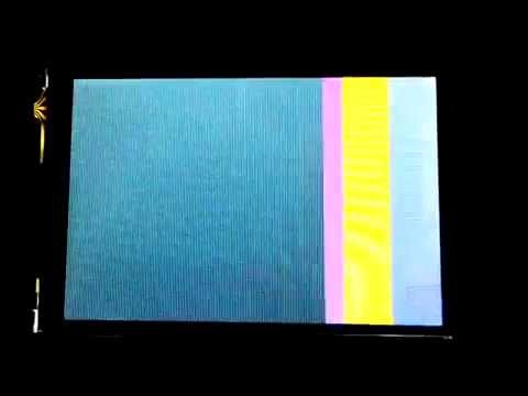
2.8" TFT LCD, unknown ID.

Pretty much doubting I will get any help with this, but here it goes:

I ordered a cheap 2.8" display to see if I could port the libraries to Arduino.
As usual, TFT's from this manufacturer never have any kind of supporting documentations, so I read the ID and go from there.

This one in Particular, however, doesn't report any ID!

here is the link for the TFT:

Image:

And supporting software:

Notes:

The Adafruit software does not support this TFT, however the pinouts are correct and should retrieve the ID.
All tested on a Arduino Uno (TFT shield plugs directly on the Uno).

The reported ID:

8 Bit LCD test!
Unknown driver chip 0

For anything that I may have forgotten, please ASK.

That Amazon site has a link (in Q&A) which contains some Arduino folders.
Tried that yet ?

Yes I did.

Those Libraries have been verified has being a very old ST7781 version, which makes sense, as the manufacturer website
http://www.mcufriend.com/products.htm claims the display to be based on this same controller.

So Far I have tried (tested with a functional display of each type, in 8 bit mode):
ILI9327
ST7781
ILI9320
ILI9325
SSD1289

and loaded the software for those specific displays but no real display to test

SPFD5408
HX8347
S6D0139 (Reported here -> Looking for LCD GURU - s6d0139 driver need init tips - 2.6" LCD from ebay - Displays - Arduino Forum)

I start to believe this is a Phone LCD. On those the ID's are hidden.
Andy is a good source for such things but his displays are all 16bit interfaced.

I've posted a message about this display in another thread. It looks like the 2.8 inch screen I have now got working with the UNO.

http://forum.arduino.cc/index.php?PHPSESSID=83rkco5pkdd9gaqsd1kag64l90&topic=221685.15

I've included a copy of the library and an example file. I initially got it working but the colours were far too bright, almost white. I then modded the library to stop it sending specific codes to the display.

Hope it helps

Hi. I also got this display (off ebay). I found a contact email on the mcufriend.com website, so i emailed them, and after a few exchanges i was sent a sketch called _8347uno that makes the screen go black instead of white. i count this as some progress, however im not very knowledgeable on how the code works. perhaps somebody can use it as a basis to make a library to make these work?

i looked up 8347 and found there is are controllers with that number, and i tried the UTFT set up for the HX8347A controller with no luck, but im hoping someone with more knowledge than me can figure it out.

the code they sent me was

#define LCD_RD   A0
#define LCD_WR   A1     
#define LCD_RS   A2        
#define LCD_CS   A3       
#define LCD_REST A4

void Lcd_Writ_Bus(unsigned char VH)
{
  unsigned int i,temp,data; 
  data=VH;
  for(i=8;i<=9;i++)
  {
    temp=(data&0x01);
    if(temp)
      digitalWrite(i,HIGH);
    else
      digitalWrite(i,LOW);
    data=data>>1;
  }	
  for(i=2;i<=7;i++)
  {
    temp=(data&0x01);
    if(temp)
      digitalWrite(i,HIGH);
    else
      digitalWrite(i,LOW);
    data=data>>1;
  }	 

  digitalWrite(LCD_WR,LOW);
  digitalWrite(LCD_WR,HIGH);
}


void Lcd_Write_Com(unsigned char VH)  
{   
  digitalWrite(LCD_RS,LOW);
  Lcd_Writ_Bus(VH);
}

void Lcd_Write_Data(unsigned char VH)
{
  digitalWrite(LCD_RS,HIGH);
  Lcd_Writ_Bus(VH);
}

void Lcd_Write_Com_Data(unsigned char com,unsigned char dat)
{
  Lcd_Write_Com(com);
  Lcd_Write_Data(dat);
}

void Address_set(unsigned int x1,unsigned int y1,unsigned int x2,unsigned int y2)
{
	Lcd_Write_Com_Data(0x02,x1>>8);
	Lcd_Write_Com_Data(0x03,x1);
	Lcd_Write_Com_Data(0x04,x2>>8);
	Lcd_Write_Com_Data(0x05,x2);
	Lcd_Write_Com_Data(0x06,y1>>8);
	Lcd_Write_Com_Data(0x07,y1);
	Lcd_Write_Com_Data(0x08,y2>>8);
	Lcd_Write_Com_Data(0x09,y2);
	Lcd_Write_Com(0x22); 							 
}

void Lcd_Init(void)
{
  digitalWrite(LCD_REST,HIGH);
  delay(5); 
  digitalWrite(LCD_REST,LOW);
  delay(15);
  digitalWrite(LCD_REST,HIGH);
  delay(15);

  digitalWrite(LCD_CS,HIGH);
  digitalWrite(LCD_WR,HIGH);
  digitalWrite(LCD_CS,LOW);  //CS

    Lcd_Write_Com_Data(0x46,0x91);
	Lcd_Write_Com_Data(0x47,0x11);
	Lcd_Write_Com_Data(0x48,0x00);
	Lcd_Write_Com_Data(0x49,0x66);
	Lcd_Write_Com_Data(0x4a,0x37);
	Lcd_Write_Com_Data(0x4b,0x04);
	Lcd_Write_Com_Data(0x4c,0x11);
	Lcd_Write_Com_Data(0x4d,0x77);
	Lcd_Write_Com_Data(0x4e,0x00);
	Lcd_Write_Com_Data(0x4f,0x1f);
	Lcd_Write_Com_Data(0x50,0x0f);
	Lcd_Write_Com_Data(0x51,0x00);

	//240x320 window setting
	Lcd_Write_Com_Data(0x02,0x00); // Column address start2
	Lcd_Write_Com_Data(0x03,0x00); // Column address start1
	Lcd_Write_Com_Data(0x04,0x00); // Column address end2
	Lcd_Write_Com_Data(0x05,0xef); // Column address end1
	Lcd_Write_Com_Data(0x06,0x00); // Row address start2
	Lcd_Write_Com_Data(0x07,0x00); // Row address start1
	Lcd_Write_Com_Data(0x08,0x01); // Row address end2
	Lcd_Write_Com_Data(0x09,0x3f); // Row address end1

	// Display Setting
	Lcd_Write_Com_Data(0x01,0x06); // IDMON=0, INVON=1, NORON=1, PTLON=0
	Lcd_Write_Com_Data(0x16,0xC8); // MY=0, MX=0, MV=0, ML=1, BGR=0, TEON=0   0048
	Lcd_Write_Com_Data(0x23,0x95); // N_DC=1001 0101
	Lcd_Write_Com_Data(0x24,0x95); // PI_DC=1001 0101
	Lcd_Write_Com_Data(0x25,0xFF); // I_DC=1111 1111

	Lcd_Write_Com_Data(0x27,0x02); // N_BP=0000 0010
	Lcd_Write_Com_Data(0x28,0x02); // N_FP=0000 0010
	Lcd_Write_Com_Data(0x29,0x02); // PI_BP=0000 0010
	Lcd_Write_Com_Data(0x2a,0x02); // PI_FP=0000 0010
	Lcd_Write_Com_Data(0x2C,0x02); // I_BP=0000 0010
	Lcd_Write_Com_Data(0x2d,0x02); // I_FP=0000 0010

	Lcd_Write_Com_Data(0x3a,0x01); // N_RTN=0000, N_NW=001    0001
	Lcd_Write_Com_Data(0x3b,0x00); // P_RTN=0000, P_NW=001
	Lcd_Write_Com_Data(0x3c,0xf0); // I_RTN=1111, I_NW=000
	Lcd_Write_Com_Data(0x3d,0x00); // DIV=00
	delay(1);
	Lcd_Write_Com_Data(0x35,0x38); // EQS=38h
	Lcd_Write_Com_Data(0x36,0x78); // EQP=78h
	Lcd_Write_Com_Data(0x3E,0x38); // SON=38h
	Lcd_Write_Com_Data(0x40,0x0F); // GDON=0Fh
	Lcd_Write_Com_Data(0x41,0xF0); // GDOFF

	// Power Supply Setting
	Lcd_Write_Com_Data(0x19,0x49); // CADJ=0100, CUADJ=100, OSD_EN=1 ,60Hz
	Lcd_Write_Com_Data(0x93,0x0F); // RADJ=1111, 100%
	delay(1);
	Lcd_Write_Com_Data(0x20,0x40); // BT=0100
	Lcd_Write_Com_Data(0x1D,0x07); // VC1=111   0007
	Lcd_Write_Com_Data(0x1E,0x00); // VC3=000
	Lcd_Write_Com_Data(0x1F,0x04); // VRH=0011

	//VCOM SETTING
	Lcd_Write_Com_Data(0x44,0x4D); // VCM=101 0000  4D
	Lcd_Write_Com_Data(0x45,0x0E); // VDV=1 0001   0011
	delay(1);
	Lcd_Write_Com_Data(0x1C,0x04); // AP=100
	delay(2);

	Lcd_Write_Com_Data(0x1B,0x18); // GASENB=0, PON=0, DK=1, XDK=0, VLCD_TRI=0, STB=0
	delay(1);
	Lcd_Write_Com_Data(0x1B,0x10); // GASENB=0, PON=1, DK=0, XDK=0, VLCD_TRI=0, STB=0
	delay(1);
	Lcd_Write_Com_Data(0x43,0x80); //set VCOMG=1
	delay(2);

	// Display ON Setting
	Lcd_Write_Com_Data(0x90,0x7F); // SAP=0111 1111
	Lcd_Write_Com_Data(0x26,0x04); //GON=0, DTE=0, D=01
	delay(1);
	Lcd_Write_Com_Data(0x26,0x24); //GON=1, DTE=0, D=01
	Lcd_Write_Com_Data(0x26,0x2C); //GON=1, DTE=0, D=11
	delay(1);
	Lcd_Write_Com_Data(0x26,0x3C); //GON=1, DTE=1, D=11

	// INTERNAL REGISTER SETTING
	Lcd_Write_Com_Data(0x57,0x02); // TEST_Mode=1: into TEST mode
	Lcd_Write_Com_Data(0x95,0x01); // SET DISPLAY CLOCK AND PUMPING CLOCK TO SYNCHRONIZE
	Lcd_Write_Com_Data(0x57,0x00); // TEST_Mode=0: exit TEST mode
	Lcd_Write_Com_Data(0x21,0x00);
	Lcd_Write_Com(0x22);   
    digitalWrite(LCD_CS,HIGH);
}

void H_line(unsigned int x, unsigned int y, unsigned int l, unsigned int c)                   
{	
  unsigned int i,j;
  Lcd_Write_Com(0x02c); //write_memory_start
  digitalWrite(LCD_RS,HIGH);
  digitalWrite(LCD_CS,LOW);
  l=l+x;
  Address_set(x,y,l,y);
  j=l*2;
  for(i=1;i<=j;i++)
  {
    Lcd_Write_Data(c);
  }
  digitalWrite(LCD_CS,HIGH);   
}

void V_line(unsigned int x, unsigned int y, unsigned int l, unsigned int c)                   
{	
  unsigned int i,j;
  Lcd_Write_Com(0x02c); //write_memory_start
  digitalWrite(LCD_RS,HIGH);
  digitalWrite(LCD_CS,LOW);
  l=l+y;
  Address_set(x,y,x,l);
  j=l*2;
  for(i=1;i<=j;i++)
  { 
    Lcd_Write_Data(c);
  }
  digitalWrite(LCD_CS,HIGH);   
}

void Rect(unsigned int x,unsigned int y,unsigned int w,unsigned int h,unsigned int c)
{
  H_line(x  , y  , w, c);
  H_line(x  , y+h, w, c);
  V_line(x  , y  , h, c);
  V_line(x+w, y  , h, c);
}

void Rectf(unsigned int x,unsigned int y,unsigned int w,unsigned int h,unsigned int c)
{
  unsigned int i;
  for(i=0;i<h;i++)
  {
    H_line(x  , y  , w, c);
    H_line(x  , y+i, w, c);
  }
}
int RGB(int r,int g,int b)
{return r << 16 | g << 8 | b;
}
void LCD_Clear(unsigned int j)                   
{	
  unsigned int i,m;

  Lcd_Write_Com(0x022); //write_memory_start
  digitalWrite(LCD_RS,HIGH);
  digitalWrite(LCD_CS,LOW);
 // Address_set(0,0,320,240);

  for(i=0;i<320;i++)
    for(m=0;m<240;m++)
    {
      Lcd_Write_Data(j);

    }
  digitalWrite(LCD_CS,HIGH);   
}

void setup()
{
  for(int p=2;p<10;p++)
  {
    pinMode(p,OUTPUT);
  }
  pinMode(A0,OUTPUT);
  pinMode(A1,OUTPUT);
  pinMode(A2,OUTPUT);
  pinMode(A3,OUTPUT);
  pinMode(A4,OUTPUT);
  digitalWrite(A0, HIGH);
  digitalWrite(A1, HIGH);
  digitalWrite(A2, HIGH);
  digitalWrite(A3, HIGH);
  digitalWrite(A4, HIGH);
  Lcd_Init();
 LCD_Clear(0xf800);
}

void loop()
{  

 /* for(int i=0;i<1000;i++)
  {
    Rect(random(300),random(300),random(300),random(300),random(65535)); // rectangle at x, y, with, hight, color
  }
  */
//  LCD_Clear(0xf800);
}

Andrew8098:
Hi. I also got this display (off ebay). I found a contact email on the mcufriend.com website, so i emailed them, and after a few exchanges i was sent a sketch called _8347uno that makes the screen go black instead of white. i count this as some progress, however im not very knowledgeable on how the code works. perhaps somebody can use it as a basis to make a library to make these work?

i looked up 8347 and found there is are controllers with that number, and i tried the UTFT set up for the HX8347A controller with no luck, but im hoping someone with more knowledge than me can figure it out.

the code they sent me was

...

That was lucky. I too, contacted them as I cant download the files on their website (perhaps china access only?) but never got to hear from them. Ill give it a try, hopefully the init code can tell us what display this is, if it is the right one.

You were given the code for the HX8347a.

The display is initialized and shows some stuff but not correctly, so it can either be:

Wrong init commands
Wrong code (LCD is initialized correctly but data is not sent to the right registers)

The odd thing is that the adafruit sketch for this same chip does not work. Perhaps the pins are re-arranged differently?

Hi, Thanks for this, i've spent the last 3 days trying to get this lcd to work. also if its any help, un-commenting out the last 'void loop()' section, gets blue rectangles to appear on the screen..

void loop()
{  

for(int i=0;i<1000;i++)
 {
   Rect(random(300),random(300),random(300),random(300),random(65535)); // rectangle at x, y, with, hight, color
 }
 
 LCD_Clear(0xf800);
}

Like all the people who posted here, I also bought this 10days back and spent lot of time with no result.

mogness post helped me to see some light.

Yes, display shows rectangle and that means it is getting initialized and basically the commands are working.

I just drawn 4 rectangles and it is shown in the display (rather than letting the code draw random ones).

void loop(){
    Rect(20,40,40,40,128); // rectangle at x, y, with, hight, color
    Rect(60,100,100,120,255);
    Rect(25,45,45,45,64);
    Rect(65,105,105,125,384);
while(1){};
//  LCD_Clear(0xf800);
}

But the display is not very clear. Blue colour is bit ok but the other two is not so visible. Also the display is bit blueyish.

I think with some information like it is getting initialized and some basic command working, some experienced people should be able to figure out how to make it work fully.

I will also keep working on it and update.

Note :
-Code I tried was the one posted by Andrew8098
-Picture of the display also I am showing here (it is not so clear, it is night here in my place and I am not too good in taking photo)
-For me also the code I got it from seller was showing no ID i.e unknown driver chip 0 as mentioned in casemod's post

20141024_205239 (320x240).jpg

Hi, I also have this lcd, I have seen videos on youtube with the adapter working, apparently the library UTFT v2.77b ILI9327 8bit is required. someone has that library, I searched with no results.

I think though the PCB has the printing like "www.mcufriend.com" and "2.8" TFT LCD Shield", different pieces sold by them may have different controller.

I feel the piece I have is based on 8347 controller because this controller at command register address 0x67 will return 47 (as per datasheet) and I am getting 4747.

Most of the register address I see in the sample code I used to draw the rectangle matches with 8347 driver IC datasheet though the values are bit different to the sample code snippet given in the datasheet.

Further I find only blue colour is prominent; green and red are not coming properly; in fact red colour is not at all visible.

I feel it is because the colour value is written properly only for first 8bit and if you see the code below it is very clear only 8bit is written. If we could fix this then we could get all colours and slowly build the library.

void Rect(unsigned int x,unsigned int y,unsigned int w,unsigned int h,unsigned int c)
{
  H_line(x  , y  , w, c);
  H_line(x  , y+h, w, c);
  V_line(x  , y  , h, c);
  V_line(x+w, y  , h, c);
}

In the above function colour is unsigned int

void H_line(unsigned int x, unsigned int y, unsigned int l, unsigned int c)                   
{	
  unsigned int i,j;
  Lcd_Write_Com(0x02c); //write_memory_start
  digitalWrite(LCD_RS,HIGH);
  digitalWrite(LCD_CS,LOW);
  l=l+x;
  Address_set(x,y,l,y);
  j=l*2;
  for(i=1;i<=j;i++)
  {
    Lcd_Write_Data(c);
  }
  digitalWrite(LCD_CS,HIGH);   
}

In the above function also colour is unsigned int

void Lcd_Write_Data(unsigned char VH)
{
  digitalWrite(LCD_RS,HIGH);
  Lcd_Writ_Bus(VH);
}

But in the above function, the argument is unsigned char so int is passed to char, so more than 8 bit of color information may be getting lost without being sent to TFT

I am trying to fix and get all colours but not successful so far....just learning

May be somebody who is familiar with how these driver ICs work can help...

Tried whole day without success.
Only getting blue colour and to a certain extent a dull green colour.

Looks like there is something wrong in the way we have to write to GRAM.

Went through whole HX8347 datasheet but could not figure out. Even getting doubt whether the driver is actually HX8347.

Setting aside for sometime till someone finds a way out......

I bought this from WiseNews electronic firms through www.yoybuy.com at taobao shop http://item.taobao.com/item.htm?id=40990017481&spm=2014.12317209.0.0

I have written now to yoybuy for seller support to solve this.

Let me see how it goes.

Update on Nov 11 : Seller replied as they also do not know

Hello, I have this capacitive display:

I try this display with arduino UNO and it is all ok, but when I use the display with arduino MEGA 2560 the display remain white...

Can you help me?
Must I change something from arduino uno to mega?

Please answer me

Thanks

F.N.

I too bought the same display from the same supplier. After a little investigation I discovered the TFT Controller is a st7783. At least on the one supplied to me.

I installed the following libraries from the following links

Then the library from post 23 in the following link

http://forum.arduino.cc/index.php?topic=223769.15

At the moment the only issue after trying the samples is tftPaint. The TFT is 180 degrees out compared to the displayed picture.

I Just found this forum post which seems to be the same screen, haven't read through it yet, but I Thought i'd post it here so you could look for yourselves

http://forum.arduino.cc/index.php?PHPSESSID=serof6rimu5rjf9dm3auc79c11&topic=223769.0

Has there been any resolution to this? I am having the same problem, and none of the libraries have any impact.

we got the screen to display rectangles with the code posted in post #4 and un-commenting out the last 'void loop' and this created a series of random rectangles, the screen currently only displays in blue and a bit dark-green. That's about it, unless anyone has any updates

Hello everybody,
I have a question:

I have this display:

I want to load an image not from SD/card, but like file .c
I want also that the touch is ok and give me the position of the pixels on the display. (for example (x,y)).
I want that image remain on the screen and use the touch.

Thanks
F.N.

I have had some limited success merging the functions of the TFTLCD library with the code in post 4, but I am not getting anywhere with the color. Has anybody gotten anything other than blue on the display?

From what I can gather from the data sheet the RGB registers need to be set, but I am not savvy enough with dealing with registers to know how to do that.