I have an idea for a product and have put together many of the pieces but can't tie it all together. Looking for someone who is interested in helping create a product that can be marketed and sold. I need programming help. You won't get rich because its a fairly small market. It's an LDC digital sight tape for an Archery Sight. I cant pay for the help but can offer a percentage of the profit on the product.
Sounds interesting. Any more details?
Can I suggest that you ask this thread to be moved to Gigs and Collaborations ?
Click "Report to moderator" and ask for it to be moved.
I would like more details too
jeffoberle:
I have an idea for a product and have put together many of the pieces but can't tie it all together. Looking for someone who is interested in helping create a product that can be marketed and sold. I need programming help. You won't get rich because its a fairly small market. It's an LDC digital sight tape for an Archery Sight. I cant pay for the help but can offer a percentage of the profit on the product.
Help Needed to Read Digital Caliper and output data to LCD screen
There are a few places on the web where people have hacked in to digital calipers for the clock and data signals etc. to use on DRO systems.
I have included 2 attachments if you are interested
Digital Sight Scale Idea.pdf (1.3 MB)
Simple Sight Drawing with Idea.pdf (168 KB)
Definitly interested in this ![]() Please keep in mind that digital calipers do not measure absolute position, you have to set a 0-point.
Please keep in mind that digital calipers do not measure absolute position, you have to set a 0-point.
I understand this and that is covered in my attachments
This is a project I have been interested in for 2 years. I have approached some industry manufacturers who are interested in this but I need to develop a working prototype to test.
I am interested in learning and doing as much as possible myself but realize I can't do it alone and will need help. I am willing to purchase whatever pieces and parts are necessary and compensate the right person for help in developing this prototype. This is not a project that anyone will ever get rich or even make a living from so there is a limit to how much I am willing to spend to develop it.
I note that your document says
I want
to be able to place a sensor on the stationary part and another sensor on the moveable part and be able
to measure their distance apart as they are moved closer or further away from each other.
In practice, if using a Digital Caliper mechanism you only need one sensor as the caliper will measure the distance between a fixed point and a movable point assuming that a zero reference can be established
This data would be used by the algorithm to figure out each aiming point from 1 to 120 yds.
Do you have a formula that relates distance to aiming point ? I assume that it will not be a linear relationship.
I would like to do this with the LCD screen being up to 5 feet away from the sensors
Is there any point in having a remote display considering that the user will need to be able to adjust the aiming device ?
If you do not take the term "display" by the letters, there would be quite a nice option to add a speach output via app+BT. Plug in a one-ear-speaker and you do not have to look at the scale at all ![]()
Oh, other question: how much threads/inch or threads/mm does the adjusting screw have?
The speech output would be nice but the LCD will be better for now.
I don't know the threads/inch but it is very fine and has click stops. One revolution on the adjusting knob has 24 click stops and moves very little in elevation.
I do not have a formula but I know it exists. It involves measuring how many feet per second the arrow leave the bow at and the weight and drag of the arrow. I think there is a more simple way to do this by having a series of tables for different arrow speeds and the table would have a caliper measured distance from say 20 yds to 50 yds. This is very hard to explain but what I and most archers do is shoot a known short distance (20 yds) and move our sight until it is zeroed in at that distance then make a mark on the sight tape. We then move to a longer distance (40 or 50 yds) and repeat the process and make a mark. Then we take a pair of digital calipers and measure the distance on the sight tape between the 2 marks and compare this to a sheet of scaled marks until we find the one that matches. Then cut out this one and affix it to the sight and move an indicator on the sight to get it zeroed again at 30, 40 or 50. Then test and all distances between 20 and 100 are usually spot on.
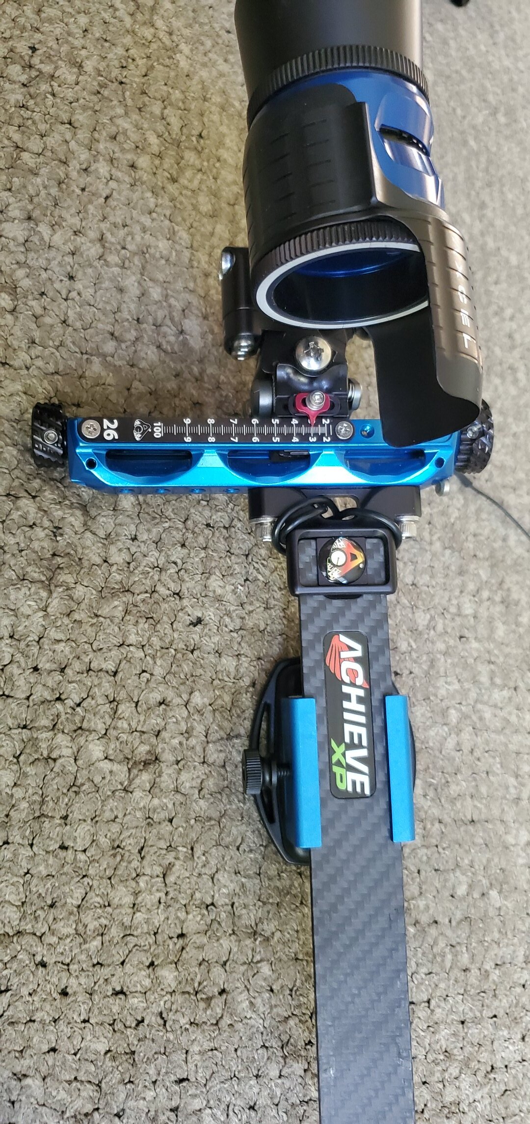
This is what the sight tapes look like. For example: My bow shoots 283 fps and tape #26 works from 20 to 100 yards for me.

Math is quite simple, the sighttape uses a scale from polynom of 2. degree. So take some sampleshots, use methode of least squares for aproximation, and you are fine.
@ the 24 clicks: can you post a photo of the actual mechanics with a scale (preferable mm)?
And another question: Am I correct when I assue that you would like to use most if not all parts from an existing archery sight (add electronics+casing and be fine)?
Exactly, whatever that means..lol
Means it's not rocket science ![]()
Would that fit the bill of the electronics? Buttons, LCD, box ...?
I generally understand the quadratic equation, it's just been many years since algebra.
That looks like it would work for a prototype, I would want the final to be smaller and sexier
Sure, but proof of concept is the forst step in product development .. and I relly like to use what's at hand ![]()
Do you have some images of the parts you like to use? And what parts of the sight you would like not to use?
This is an Arduino I have been messing with and an LCD screen with a range sensor. It does not measure precise enough but gave me some basic experience and understanding.