WDT Nano with L298N for dc motor

I have tested a nano with wdt code that puts it to sleep and wakes up every hour to run a motor via L298N module.

The problem is that the nano falls asleep saving power, but the L298N is constantly powered on by the battery pack. I was thinking of turning the power to the l298n on.off via a transistor so I was wondering if its possible/recommended:

My current setup is a single dc motor connected via L298N In1, In2 and EnA, to pins 6/7 on the nano. A 2x3.7V battery pack in series (8.44V) powers the rail which feeds:

The Nano via the Vin pin, and
The L298N via the 12V terminal.

So my thinking was, maybe I can cut off power to the L298N (8.44V rail to 12V terminal) via a transistor and only switch it on when the nano wakes up.

The 2N2222 is the only one I know really, its Icmax is 800mA. However the dc motor amperage I dont know. How should I proceed? The only thing I know about the motor is:

Rated Voltage: DC 12V
Speed(no load): 5000RPM

The L298N has a max current for both channels of 4A, so you should get a logic-level mosfet which can handle that load. mosfets are a better option than transistors. they have less voltage drop and dissipate less power as heat, which means more energy getting to your motors and less battery capacity being lost to the aether.

but yes, turning on and off peripherals using a transistor or mosfet is indeed a valid energy-saving strategy.

keep in mind too, though, that since you're powering your nano through the Vin, it has to go through the lossy 5V regulator, which will have a running consumption of a few mA.

Open question: If the OP were to take a tap off just one of the series li-po's, could they power the nano off the 3.7V bypassing the 5V regulator, and allow the full 7.4V to go to the motors? Or would that cause complications with the batteries being in series?

So something like this? Maybe put a diode in there?

FYI, you will get jumped on for your fritzing diagram. folks here don't care for them. :wink:

But no, that's all mixed up. You've still got your L298N hooked up directly to the power rail, so nothing has changed in terms of powering it on and off.

Also, you'll need a resistor between your arduino pin and base pin (pin 1) of the transistor. Not sure what value to recommend since I don't really use transistors. Plus, you've got the transistor wired wrong. I'm not 100% sure, so let someone more familiar with them than myself confirm this, but I think you'll want to remove the red wire going from VCC to the transistor's collector pin (pin 2), and connect the ground from your L298N to the collector pin instead.

And if you're asking about a flyback diode for the motors, I don't think that's necessary since you're using a an H-bridge.

And I assume you just show a 9V battery for illustrative purposes. They're pretty much worthless for actual use.

Oh My God I just realized how stupid my power - L298N wiring is. Lemme fix that.

Yes I know people here don't like fritzing but it's only because they don't consider the ease of use. It's much easier to bring up fritz ing and wire up the parts than search for them in eagle. For example, there is no L298N part in Eagle. I've made pcbs in Eagle before and it's awesome but it's faster to do some simple things in Fritzing.

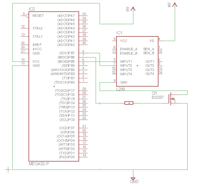
Ok so like this:

Sorry but I couldnt find the L298 or the atmega328 in the components library.

It looks like the way you corrected your fritzing diagram is the correct hook-up. The way you have it in your Eagle schematic is different. Which way do you intend to go?

In the fritzing diagram it shows that you're turning on and off power to the whole motor driver board, whereas in the Eagle schematic, you're turning on and off power to the motor's power-supply, leaving the rest of the motor driver board powered up.

You should use an ammeter to check where and when current is actually being used. I would assume that if your motors aren't turning, there's probably not current flowing on the motor-power pin, but there probably is current being used on the 5V VCC pin for motor driver even when the motors aren't turning.

Also, SparkFun has a pretty comprehensive Eagle library that contains most of their parts, including the L298N, just not as the breakout-board (that I can find).

Thanks,

I installed the libraries from SparkFun.

As for the wiring, they look the same to me, obviously thats why I made it that way...sorry.

So 9V up top goes into Vs of the L298, same as fritzing. And the GND from the L298 goes thru the mosfet, same as before.

Arent they? Or did you mean the 5V connection to the L298? That one is indeed not there before:

they're almost the same, I was looking at them wrong, but its wrong in a different way than I thought before, lol. It was far too early in the morning, and I got thrown off looking back and forth between the two. I knew something was off.....

There's an un-needed connection from the ground rail to the ground pin of the L298N. Your transistor output to the L298N ground pin should not have that side-branch going down the image to the ground rail. It should be a straight connection from the collector pin of the transistor to the GND of L298N.

Here I edited out the ground connection in question.

Oh OK I see! OK I'll give it a go

Eagle question, how come Open Recent Projects doesn't work in the sense that it wont find the projects or schematics I create?

is it looking in the right directory?

Ok Im using an FQP which Ive used before at logic levels to control the motor. I have it working such that the L298N gets power when the fet activates it via D5 and a 1k Resistor, but for some reason the motor doesn't run. I think it might be a current issue?

I need my voltmeter...btw its getting 4.85V at the L298N 12V+ and GND terminals. So the code lights up the L298N for 2 seconds as expected but it the motor doesnt run. Code:

#include <avr/wdt.h>            // library for default watchdog functions
#include <avr/interrupt.h>      // library for interrupts handling
#include <avr/sleep.h>          // library for sleep
#include <avr/power.h>          // library for power control
#include <util/delay.h>


//1. NOT SURE WHAT THIS ALL DOES
#if (defined (__AVR_ATmega328P__) || defined (__AVR_ATmega328__))
    #define UNO
    #define LED_PORT        PORTB
    #define LED_PIN         PB5
    char BOARD[]      = {"m328p"};
#endif

//2. Defines variables
#define LED 13
#define fet 5
int nbr_sleeps=0; 
//2.1 WHAT IS THIS FOR?
volatile int f_wdt=1;
//2.2 L298N VARIABLES
int enA = 10;
int in1 = 7;
int in2 = 6;
  
inline void     flash_led()     {LED_PORT |= (1 << LED_PIN); _delay_ms(30);
                                    LED_PORT &= ~(1 << LED_PIN);}


ISR(WDT_vect){
        // disables wdt upon wake up so it wont fire accidentally while we do stuff before sleep again
        wdt_disable();
}

void setup(){
  //5.1 L298N setup
  pinMode(enA, OUTPUT);
  pinMode(in1, OUTPUT);
  pinMode(in2, OUTPUT);    
  pinMode(fet, OUTPUT);
  digitalWrite(fet, LOW);
  pinMode(LED, OUTPUT);
}


void sleep(){
  nbr_sleeps ++;
  ADCSRA = 0; 
  MCUSR = 0;                       // reset status register flags
  WDTCSR |= 0b00011000;            // Set WDCE (5th from left) and WDE (4th from left) to enter config mode,
  WDTCSR =  0b01000000 | 0b100001; // set WDIE: interrupt enabled
  wdt_reset();
  set_sleep_mode(SLEEP_MODE_PWR_DOWN);    
  noInterrupts ();           // timed sequence follows
  sleep_enable(); //not needed
  // turn off brown-out enable in software
  MCUCR = bit (BODS) | bit (BODSE);
  MCUCR = bit (BODS); 
  interrupts ();             // guarantees next instruction executed
  sleep_cpu ();  
  flash_led();               //signal just woke up and continue loop execution...
  sleep_disable(); //not needed
}

void loop(){
  flash_led(); //signalling about to sleep
  sleep(); //sleep suff
  if (nbr_sleeps==4) runMotor();
}
//8 sec/cycle * 450 cycles = 3600 seconds = 1hr


void runMotor() {
  //Turn motor on
  flash_led(); //signal about to run motor
  //turn on mosfet
  digitalWrite(fet, HIGH);
  delay(500);
  //Now run motor
  digitalWrite(in1, HIGH);
  digitalWrite(in2, LOW);
  analogWrite(enA, 200);
  delay(2000);
  digitalWrite(in1, LOW);
  digitalWrite(in2, LOW);
  digitalWrite(fet, LOW);
  nbr_sleeps=0;
}

I'm not sure what you mean by saying that you're getting 4.85V at the 12V pin. Is that what you expected? Can you post a picture or drawing of your complete wiring setup? Without that, its hard to give further input as it could be many things.

Ok nevermind, I didnt plug in the 9V source, I had just left the USB connected to the computer so maybe it wasnt getting enough juice, which is btw why it should 4.85V or so, instead of the 8.45V.

I did discover however that a cleaned-up version of my code didnt work, seems the nano is reboots, maybe the wdt_reset() isnt reached in time, and so the runMotor() is never called. But with my old sleep code it works fine. So Id like to ask for help in cleaning up that failing code. Below are both code versions and both video links:

GOOD CODE======================================================

#include <avr/wdt.h>            // library for default watchdog functions
#include <avr/interrupt.h>      // library for interrupts handling
#include <avr/sleep.h>          // library for sleep
#include <avr/power.h>          // library for power control
#include <util/delay.h>


//1. DEFINE LED PIN FOR COND COMP
#if (defined (__AVR_ATmega328P__) || defined (__AVR_ATmega328__))
    #define UNO
    #define LED_PORT        PORTB
    #define LED_PIN         PB5
    char BOARD[]      = {"m328p"};
#endif

//2. Defines variables
#define LED 13
#define fet 5
int nbr_sleeps=0; 
int enA = 10;
int in1 = 7;
int in2 = 6;
  
inline void     flash_led()     {LED_PORT |= (1 << LED_PIN); _delay_ms(30);
                                    LED_PORT &= ~(1 << LED_PIN);}


//3. Interrupt Service Routine - disable wdt as soon as comeback
ISR(WDT_vect){
        // disables wdt upon wake up so it wont fire accidentally while we do stuff before sleep again
        wdt_disable();
        //does it get re-enabled by sleep_mode()?  wdt_reset() might be a better idea.
}

//5. Set some other stuff up in setup
void setup(){
  //5.1 L298N setup
  pinMode(enA, OUTPUT);
  pinMode(in1, OUTPUT);
  pinMode(in2, OUTPUT);    
  pinMode(fet, OUTPUT);
  digitalWrite(fet, LOW);
  pinMode(LED, OUTPUT);
}

//6. These must be called each loop
void sleep(){
   nbr_sleeps ++;
   MCUSR &= ~(1<<WDRF); //or MCUSR = 0;
   ADCSRA = 0; //turns off ADC
   WDTCSR |= (1<<WDCE) | (1<<WDE); //or WDTCSR = bit (WDCE) | bit (WDE);
   WDTCSR = 1<<WDP0 | 1<<WDP3;// or WDTCSR = bit (WDIE) | bit (WDP3) | bit (WDP0);
   WDTCSR |= _BV(WDIE);
   wdt_reset();
   set_sleep_mode(SLEEP_MODE_PWR_DOWN);  
   noInterrupts(); 
   sleep_enable();
   // turn off brown-out enable in software
   MCUCR = bit (BODS) | bit (BODSE);
   MCUCR = bit (BODS); 
   interrupts();             // guarantees next instruction executed
   sleep_mode();
   flash_led();
   //EXECUTION AFTER ISR RESUMES HERE...
   sleep_disable();
}
void loop(){
  flash_led(); //signalling about to sleep
  sleep(); //sleep suff
  if (nbr_sleeps==4) runMotor();
}
//8 sec/cycle * 450 cycles = 3600 seconds = 1hr


void runMotor() {
  //Turn motor on
  flash_led(); //signal about to run motor
  //turn on mosfet
  digitalWrite(fet, HIGH);
  delay(500);
  //Now run motor
  digitalWrite(in1, HIGH);
  digitalWrite(in2, LOW);
  analogWrite(enA, 200);
  delay(2000);
  digitalWrite(in1, LOW);
  digitalWrite(in2, LOW);
  digitalWrite(fet, LOW);
  nbr_sleeps=0;
}

BAD CODE=========================================================

#include <avr/wdt.h>            // library for default watchdog functions
#include <avr/interrupt.h>      // library for interrupts handling
#include <avr/sleep.h>          // library for sleep
#include <avr/power.h>          // library for power control
#include <util/delay.h>


//1. DEFINE LED PIN FOR COND COMP
#if (defined (__AVR_ATmega328P__) || defined (__AVR_ATmega328__))
    #define UNO
    #define LED_PORT        PORTB
    #define LED_PIN         PB5
    char BOARD[]      = {"m328p"};
#endif

//2. Defines variables
#define LED 13
#define fet 5
int nbr_sleeps=0; 
int enA = 10;
int in1 = 7;
int in2 = 6;
  
inline void     flash_led()     {LED_PORT |= (1 << LED_PIN); _delay_ms(30);
                                    LED_PORT &= ~(1 << LED_PIN);}


//3. Interrupt Service Routine - disable wdt as soon as comeback
ISR(WDT_vect){
        // disables wdt upon wake up so it wont fire accidentally while we do stuff before sleep again
        wdt_disable();
        //does it get re-enabled by sleep_mode()?  wdt_reset() might be a better idea.
}
//4. Set WDT config parameters - ONCE
void configure_wdt(){
    set_sleep_mode(SLEEP_MODE_PWR_DOWN);    
    MCUSR &= ~(1<<WDRF); //or MCUSR = 0;
    ADCSRA = 0; //turns off ADC
    power_adc_disable() //PRR extras
    SPCR = 0; //turns off spi
    power_spi_disable();// turns off clock to spi PRR extras
    power_all_disable(); // PRR extras
    WDTCSR |= (1<<WDCE) | (1<<WDE); //or WDTCSR = bit (WDCE) | bit (WDE);
    WDTCSR = 1<<WDP0 | 1<<WDP3;// or WDTCSR = bit (WDIE) | bit (WDP3) | bit (WDP0);
    WDTCSR |= _BV(WDIE);
}

//5. Set some other stuff up in setup
void setup(){
  //5.1 L298N setup
  pinMode(enA, OUTPUT);
  pinMode(in1, OUTPUT);
  pinMode(in2, OUTPUT);    
  pinMode(fet, OUTPUT);
  digitalWrite(fet, LOW);
  pinMode(LED, OUTPUT);
  configure_wdt();
}

//6. Could maybe move some parameters, like ADC off back into the sleep()-loop() 
void sleep(){
   nbr_sleeps ++;
   wdt_reset();
   sleep_mode();
  //EXECUTION AFTER ISR RESUMES HERE...

}
void loop(){
  flash_led(); //signalling about to sleep
  sleep(); //sleep suff
  if (nbr_sleeps==4) runMotor();
}
//8 sec/cycle * 450 cycles = 3600 seconds = 1hr


void runMotor() {
  //Turn motor on
  flash_led(); //signal about to run motor
  //turn on mosfet
  digitalWrite(fet, HIGH);
  delay(500);
  //Now run motor
  digitalWrite(in1, HIGH);
  digitalWrite(in2, LOW);
  analogWrite(enA, 200);
  delay(2000);
  digitalWrite(in1, LOW);
  digitalWrite(in2, LOW);
  digitalWrite(fet, LOW);
  nbr_sleeps=0;
}

Video Links:

The bad video is similar but the led would blink before 8 seconds of sleep in one of the cycles, leading me to believe the Arduino was rebooted.

glad it was easy.

just to clarify, if you remove all the sleep-code and use a stripped-down program, do the motors behave as you intend?

Yes the code without sleep (using mills every 8 seconds) works fine.

But I made a compilation of sleep code snippets which works and it's the one used in the uploaded video.

But then I made a newer version of the sleep code where I tried moving somethings I thought were fine inside a one-time called function named configure_wdt() and other calls which I thought could be called every loop/sleep time but that code didn't work, that's the one called bad code.

What I wanted was to use a complete and clean version of my sleep codebut it doesn't work.

  1. Things not in bad code:
    A noInterrupts
    B sleep_enable()
    C MCUCR BODS
    D Interrupts()

  2. Differences in order:
    A flash_______________|set_sleep_mode
    B nbr________________|Mcucsr/Adcsra
    C Mcucsr/Adcsra/Wdtcsr_|power_adc_disable/Spcr
    D wdt_reset_________|power_spi_disable/power_all_disable
    E set_sleep_mode__|Wdtcsr
    F Interrupts/Bods__|flash_led()
    G sleep_mode_____|nbr
    H flash_led()_|wdt_reset()
    I sleep_disable
    |sleep_mode()

So I tracked down the issue to calling power_all_disable() without calling power_all_enable() again afterwards.

Thanks

Hey guys, Im back with trouble here. I moved over from breadboard to through hole. I cant seem to make the motor run anymore. The same setup worked on the breadboard but now fails to run the motor.

I know the code is fine because it worked before (on the breadboard). Here is the diagram:

I read the voltage between the D5 pin on the nano and GND and I get 5V on the multimeter, so I know the pin on the nano is being set to HIGH as expected.

I read the voltage between 12V of the L298 and the GND of L298 and I get 0 when nano-D5 goes high.

I read the voltage between GND and Mosfet Gate and I get 5V when nano-D5 goes high.

So it must be something else. Here are the images of my board: