I2C 1602 LCD - Menu Questions & Discussion (pics)

Hello,

I've been spending the past few days working with the I2C 1602 LCD Menu, specifically the Hitachi HD4478 16x2 LCD Display with the LCM 1602 IIC controller. This specifically part has allowed me to efficiently save space and keep my hardware tidy - anyways...

To give you a little more information about my project: I am making a machine that will allow me to do experiments and research into the production of graphene components and their underlying concepts. I welcome anyone else who would be interested, has experienced with the material, or has already produced a similar machine to chime in on some discussion (perhaps I'll make another thread? :D)

However, work first and play later:
I am having issues creating a Menu Interface for the end user to select between different modes. I have tried the one library I seem to come across the most often: MenuBackend.h

In particular I am using Revision 1.4 of this library as per the examples from: Tutorial: manage menu and LCD display with Arduino – Coagula – Giuseppe Di Cillo

The main issue: The LCD Prints the initial information I add in the void setup function. However it does not display the menu, it immediately goes to a blank screen and I cannot seem to find a work around. It must be how I wrote my code... Or one would logically deduce.

Ideally, I want to create an interface that is similar to this:

In the video, the developer shows a hierarchical menu that controls, I assume, an SD card interface.
I've contact the person who uploaded that video to see if they would let me look at the code or at least help me troubleshoot my problems.

I will also need to be able to adjust values, or even enter values from a number pad, in this video the developer uses a three button interface to select modes/values for a DSLR Shutter Intervalometer:

I would also like to be able to display the brackets around the "highlighted" value. That or do a bitmap highlight of the character (more complex yet neat looking)

Now time to look at what I've been doing... Understand that the code compiles without errors and there are some things I'm trying to do, specifically change a blinking LED's delay values using integers where I just have not figured out.

Here is the code I've written up:

(400+ Lines)

For the sake of convenience I will paste the menu hierarchy again to itself:

/*===============================================================
|| Simplified menu test...
|| /root
||    |_uptime
||    |_settings
||    |        |_Blink LED
||    |                  |_d100 (delay for 100ms)
||    |                  |_d200 (delay for 200ms)
||    |                  |_d300 (delay for 300ms)
||    |                  |_d400 (delay for 400ms)
||    |_reset
\\=============================================================*/

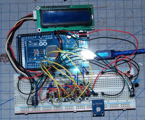
Lastly, it wouldn't be nice to just NOT show the hardware. Here is what I am working with at a glance. If needed I can quickly draw up a schematic in Fritzing:


These are 6 NO Debounce buttons I salvaged from a VCR

I've gone over what I am trying to accomplish so here are
Questions:
(1) MenuBackend.h seems to be an okay library. However the documentation I've found on it is old and seems to be in a state of "If you have a problem tell the developer, they'll get back to you maybe." Seeing as some of the last threads I found regarding MenuBackend.h issues date back to 2010. :expressionless: Where can I find decent documentation of this library? Is there a better library out there for what I am trying to achieve with similar structure?

(2) Is there a way to create a hardware defined debounce for the buttons I am using? This would make my script a little bit more efficient. Maybe someone could just point me in the direction of a thread or blog that has a schematic I could use?

(3) Is the I2C address of the LCD screen fixed, as in will it always be 0x27 with the LCM 1602 IIC controller or can this address be changed? I cannot seem to connect the LCD over this address when I am using the pull up resistors on the I2C Bus. Please note that I currently have 3 I2C devices involved with this project and I expect the addition of more when it comes to providing safety features.

I do not expect anyone to write the code for me. I do take into consideration that yes I am a novice, (new to Arduino), to coding, and I've tried to cut scripts from other sources and adapt it to what I want to do.

Thanks for any help you may be able to give, and certainly thanks for reading.
Let me know if you have any other questions regarding the project itself or the issue(s).

edit: Images stretched screen

Sorry if I am unhelpful regarding the menu.

cha0x:
(2) Is there a way to create a hardware defined debounce for the buttons I am using? This would make my script a little bit more efficient. Maybe someone could just point me in the direction of a thread or blog that has a schematic I could use?

The whole point of using a microcontroller is that it has "all the time in the world" to "waste" doing such mundane things as debouncing. If you are using a menu, you are waiting for user input and pretty much by definition, not doing anything else, so you might as well pay attention to the debouncing.

As to the details, firstly, I notice you have your (salvaged) pushbuttons connected to Vcc. Any useful reason for this? I hold that it is always safer to have such things to ground, in which case you do not need pull-up resistors as you can use the internal pull-ups of the MCU - that is what they are for.

Now to perform the debouncing, I suggest:

In order to poll and debounce eight inputs, the proper way is on each pass through the master loop (and if a new millisecond has since passed), to step through each index of the multiplexer, shifting in sequence the corresponding pushbutton state into successive bits of a byte value which then represents the combined value of the eight buttons.

You then compare this value to the previous state which you read on the last poll; if it differs then you reset the debounce count variable to its maximum - say, 20 - update this new value as the "previous" value and complete this section of code (back into the main loop). If the (byte) value just read is the same as the "previous" value read, you look at the debounce counter to see whether it is zero or not. If it is not zero, this means that the value has not been stable for a full debounce period (20 milliseconds) so you simply decrement the debounce counter and complete this section of code.

Finally, if the debounce counter is zero, then the value clearly has been stable for a full debounce period so you then compare it to the "last stable state" that you have noted (in a variable). If it is exactly the same as the last stable state, then clearly nothing has changed and you just complete this section of code, but if differs from the last stable state then you conclude that this is a new stable state which should be acted upon, so you examine and act upon each bit which differs from that last state, re-writing the "last" state to match the bit acted upon until the "last" state now matches the current state and you move on from there.

The importance of this is that it debounces eight (extensible to essentially any multiple of eight) inputs at a time, such as the code I wrote to service the keyboard of the Tandy TRS-80 "color computer" back in the 1980s.

cha0x:
(3) Is the I2C address of the LCD screen fixed, as in will it always be 0x27 with the LCM 1602 IIC controller or can this address be changed? I cannot seem to connect the LCD over this address when I am using the pull up resistors on the I2C Bus. Please note that I currently have 3 I2C devices involved with this project and I expect the addition of more when it comes to providing safety features.

Can't tell, as you have not illustrated what sort of "backpack" you are using on your LCD(s). Many (?most) have three address jumpers, either as solder jump pads - either two or three pads for each - or six apparently innocuous unused "thrus" into which you can solder pins and jumpers.

Paul__B,

The whole point of using a microcontroller is that it has "all the time in the world" to "waste" doing such mundane things as debouncing. If you are using a menu, you are waiting for user input and pretty much by definition, not doing anything else, so you might as well pay attention to the debouncing.

Regarding this, I suppose. I also had the same thought but just a curiosity.

The buttons are also wired to ground. I followed the schematic from the tutorial link I shared. Only I wired the buttons to digital I/O pins 2-7

Can't tell, as you have not illustrated what sort of "backpack" you are using on your LCD(s). Many (?most) have three address jumpers, either as solder jump pads - either two or three pads for each - or six apparently innocuous unused "thrus" into which you can solder pins and jumpers.

The backpack on the LCD is a Funduino brand LCM 1602 IIC.

I do see the address jumpers on the back and wondered what they were for. I guess that answers it...
I contacted the supplier before about getting more information about this particular board as the download link for the datasheet on their website was broken. I'll need to try contacting them again or seeing if I could find another place/tutorial that has more information.

Thanks Paul.

cha0x:
The buttons are also wired to ground. I followed the schematic from the tutorial link I shared. Only I wired the buttons to digital I/O pins 2-7

So you have your buttons wired to Vcc rather than ground. My suggestion is to wire them to ground, and you do not then really need the resistors - which would then be wired as pull-ups to Vcc - if you enable the built-in pull-up function of the Arduino. Of course you need to swap "high" and "low" in the code which deals with the buttons, but that should not be a problem.

My main reason for suggesting this is that it avoids wiring to the buttons themselves carrying the Vcc - safer when each wire is either ground or does no damage if it happens to get shorted to ground, particularly where the wires happen to travel some distance from the board.

cha0x:
The backpack on the LCD is a Funduino brand LCM 1602 IIC.

Ah, that one has caused people some concern in recent discussions, mainly because of the confusing labelling where "GND" and "VCC" appear adjacent to a link which is obviously shorted and in fact serves to enable the back-light, having nothing to do with either Vcc or ground. Some consideration reveals that these labels actually correspond to the four partially obscured and presently unused "thru"s which mirror the "GND", "VCC", "SDA", "SCL" on the other edge of the board and which could be used to chain boards - if you altered the address with the jumpers below the potentiometer.

I notice two other pairs of "thru"s on this board whose function I could not pick before but on checking pictures on eBay, the two above the potentiometer would appear to be a jumper to permanently ground the "E" - enable line on the LCD (not sure how useful that would be at all) and the one to the right of the (left-hand) "SCL" label is the interrupt request pin of the PCF8574. I have yet to figure out what the one adjacent to the "SDA" is and do not have a specimen of that board; though it (clone with the "Funduino" and "HOYA" markings not quite erased) is not that expensive (:smiley: - AU $2.61), haven't fancied picking one up on eBay just to examine the connections - but (hang the expense!), I just ordered one on eBay so in the new year I should be able to tell all. :smiley:

cha0x:
I do see the address jumpers on the back and wondered what they were for. I guess that answers it...
I contacted the supplier before about getting more information about this particular board as the download link for the datasheet on their website was broken. I'll need to try contacting them again or seeing if I could find another place/tutorial that has more information.

If it is working with the initialisation part of the code, then presumably you actually have the address and pin connections correct already and do not need to know anything else about the board. To alter the address, just solder appropriate links over the (three) address positions, my initial suggestion was that you could try jumpering different combinations and use the "I2Cscanner" sketch to figure out what address results, but actually, A0 is the link nearest the IC itself, so jumpering just that will drop the address from 27 to 26 and the others follow from that. (Jumpering the middle one reduces the address by two, and the right hand one by four, and all combinations thereof.)

To get new addresses for the fonduino clone you can short it this way:

to the right of fonduino text and to the left of LD1, just below the potentiometer you have three unsoldered pins:

the one just to the right of Funduino and below potentiometer, in a vertical line, will give address 0x26 (shorted alone), the next one shorted alone will give 0x25, the next one shorted alone will give 0x23, I have to suppose that since the sequence is:

0x1
0x2
0x4

you can have up to:
8 possible combinations, as in other schemes with similar hardware.

Yep, that's pretty much what I explained.