Most forum members generally read the forum on phones & tablets, so can't view a zip file. Plus there's the danger of viruses...
I will do you a favour and post your files according to forum guidelines.
Here's the code:
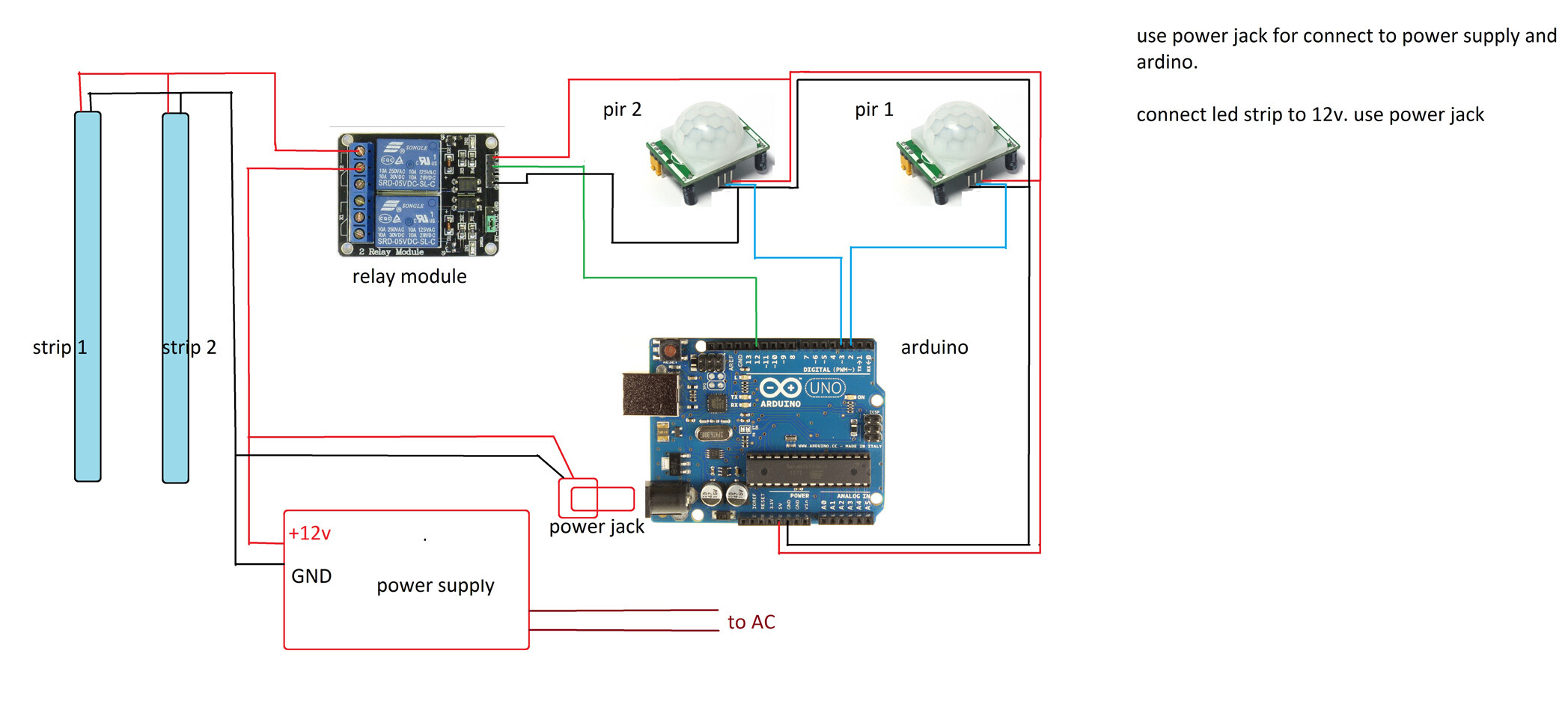
#define pirPin   2    // connect senosr 1 pin to arduino digital pin 2
#define pirPin2  3    // connect senosr 2 pin to arduino digital pin 3
#define relayPin  12  // attach relay pin to arduino digital pin 12

// variables..........
int timePeriod = 300;  // set light active time period in seconds.     it set 5 minute
int mode = 0;
//......................

// variable for motion detection.........................
int calibrationTime = 3;
long unsigned int lowIn;
long unsigned int lowIn2;
long unsigned int pause = 1000;
boolean lockLow = true;
boolean lockLow2 = true;
boolean takeLowTime;
boolean takeLowTime2;

long unsigned int activeTime = 0;
long unsigned int timer = 0;
//.......................................................


void setup(){
  Serial.begin(9600);
  pinMode(pirPin, INPUT_PULLUP);  // set pir pin 1 input
  pinMode(pirPin2, INPUT_PULLUP); // set pir pin 2 input
  pinMode(relayPin, OUTPUT);      // set relay pin output
  digitalWrite(relayPin,LOW);     // set relay pin Low (deactive)
  digitalWrite(pirPin, HIGH);
  digitalWrite(pirPin2, HIGH);

  //give the sensor some time to calibrate...............
  Serial.print("calibrating sensors ");
    for(int i = 0; i < calibrationTime; i++){
      Serial.print(".");
      delay(1000);
      }
    Serial.println(" done");
    Serial.println("SENSORS ACTIVE");
//........................................................

// set pir pins to interrupt mode......
   attachInterrupt(digitalPinToInterrupt(pirPin), functionPir01, RISING);   // if pir sensor 1 go low, run "functionPir01"
   attachInterrupt(digitalPinToInterrupt(pirPin2), functionPir02, RISING);  // if pir sensor 2 go low, run "functionPir02"
  }


void functionPir01 () {
// if pir pin 1 go active.....
 if ( timer > 1000) {
       if(lockLow){
          lockLow = false;
         Serial.println("---");
         Serial.println("Sensor 01 motion detected at ");
         delay(100);
         if ( mode == 0 ) {
            digitalWrite(relayPin, HIGH); // set relay high. ( active )
            activeTime = timer;
            mode = 1;
          }
         delay(50);
         }
         takeLowTime = true;
 }
}

void functionPir02 () {
// if pir pin 1 go active.....
  if ( timer > 1000) {
       if(lockLow2){
          lockLow2 = false;
         Serial.println("---");
         Serial.println("Sensor 02 motion detected at ");
         delay(100);
         if ( mode == 0 ) {
            digitalWrite(relayPin, HIGH); // set relay high. ( active )
            activeTime = timer;
            mode = 1;
          }
         delay(50);
         }
         takeLowTime2 = true;
  }
}


void loop(){

  timer = millis(); // timer
// pir sensor function............................................
     if(digitalRead(pirPin) == HIGH){
       if(takeLowTime){
        lowIn = millis();
        takeLowTime = false;
        }

       if(!lockLow && millis() - lowIn > pause){
           lockLow = true;
           delay(50);
           }
       }

     if(digitalRead(pirPin2) == HIGH){
       if(takeLowTime2){
        lowIn2 = millis();
        takeLowTime2 = false;
        }
       if(!lockLow2 && millis() - lowIn2 > pause){
           lockLow2 = true;
           delay(50);
           }
       }
//..................................................................


// for relay controller............................
       if ( mode == 1 ) {
          if ( timer > ( (timePeriod * 1000) + activeTime )) { // lights active time check
            digitalWrite(relayPin, LOW); //lights off
            mode = 0;
            Serial.println(" set led low ");
          }
       }
  }
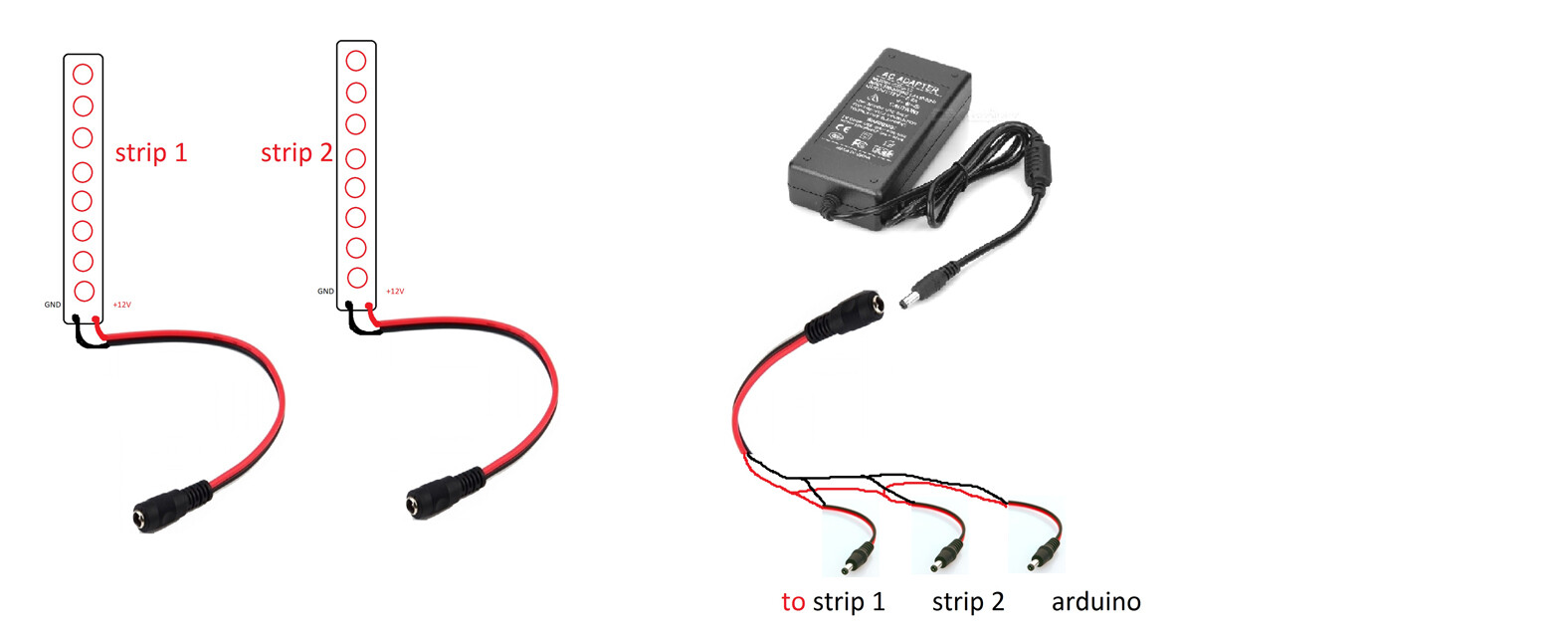
And here are the diagrams:
And the parts list:
Parts list…………………….
- Arduino Uno Board - 1
- PIR Motion Sensors - 2
- Relay module - 1
- Led Strip - 2
- Power Supply - 1
- Jumper wires
- Power jack
and want wires, soldering iron
Use diagram for connect devices.If you have any question problem contact me first.
Project is done give me a 5 stars best feedback.
Thank you.
Ardutech.