Some people put the resistor as described above some change the position and move it between LED and GND. I think it a bit more failure save to put the series resistor between Vcc and the LED. But correct me if I'm wrong.
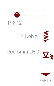
For programming this hardware setup is intuitive because HIGH switches the light on and LOW off.
Much less often you can find
Vcc -> Resistor -> LED -> PIN(x)
In this case LOW switches the light on and HIGH off. From a UX perspective I woud prefere the first version. But is there any electronic benefit to prefere the one or the other version?
Someone answered this recently as a by-the-way on another thread: I think it was AWOL or Grumpy_Mike.
IIRC, the second method is preferred since it sinks the current to the i/o pin, but I daresay someone will confirm that (or tell me I have that back-asswards). Yes the programming is less intuitive since low is "on" but that so-called "active low" is common and easy to cater for in code anyway.
But the order of led-resistor or resistor-led matters in neither case since it's a series circuit.
in general a port with mos "totem output" is able to sink more current than sourcing.
it's because the Nmos at the low side is better driven than the one at the high side. (gate voltage)
so it's best to have the led connected between the VCC and the output port if you want to have the highest current available and if your led is like a blue/white/turquoise one.
With these colors the Vf is very high, near 2.8 -> 3.5v and you must have the highest voltage available to drive them correctly. a red or standard green (570nm) have a lower Vf, near 1.6 -> 2v
but you can read the microcontroller datasheet at the "Voh and Vol voltage function of sink/source current".
in general a port with mos "totem output" is able to sink more current than sourcing.
This is "common knowledge", but used to be more true in the past than it is today. If you look at the d/s for the mega328, you'll see that source and sink characteristics are almost the same. Eg, Fig 29-160 and 29-162 in doco Rev. 8161D–AVR–10/09.
For Vcc=5V, you see that a 20mA source load pulls Vo down by about 0.52V, and a 20mA sink load pulls Vo up by about 0.47V. This gives effective Ro = 26 and 23.5 ohms in the two cases at 25degC, and these values change to 30 and 27.5 ohms at 85 degC. All in all, pretty close. You might not even notice the differences using a DMM measurement. [OTOH, it would also be interesting if someone verified this by actual measurement].
You modify these characteristics mainly by changing the dopant levels and mosfet channel geometries [length vs width], so apparently current manufacturing practices make the channels essentially equivalent - by trading off dopant and drive levels against geometry.
With these colors the Vf is very high, near 2.8 -> 3.5v and you must have the highest voltage available to drive them correctly. a red or standard green (570nm) have a lower Vf, near 1.6 -> 2v
This is also true. So, if you're running Vcc=3.3V, you need to use "sinking" mode, and tie the anode side of the Leds to +5V, not 3.3V, and the cathode side to the I/O pin. IE, you cannot effectively source current into an Led having Vf=3.5V from a 3.3V I/O pin.
this is why I've wrote "read the datasheet" to be up to date
oric_dan:
You modify these characteristics mainly by changing the dopant levels and mosfet channel geometries [length vs width], so apparently current manufacturing practices make the channels essentially equivalent - by trading off dopant and drive levels against geometry.
This is also true. So, if you're running Vcc=3.3V, you need to use "sinking" mode, and tie the anode side of the Leds to +5V, not 3.3V, and the cathode side to the I/O pin. IE, you cannot effectively source current into an Led having Vf=3.5V from a 3.3V I/O pin.
it's better to connect the anode to the +3.3V with a low resistor because if you connect it to the 5v a little current flow thru the 5v -> the led and the port clamp diode / high side mos -> to the 3.3V
5-3.3v = 1.7 -> enough to light a red led or even a white one with low current.
so it's better to use gates or transistor as level shifters to control the led in that case.
Since quite often output pins are driving higher voltages through transistors, It's simpler to have the switch on the low side than the high side. So it's just more conventional to switch the low side of a device.
for my designs I prefer to control some important things like power etc at the low level.
it's because when a microrontroller is in "reset" all the ports goes to the high level even if now they are floating but not all.
so to avoid a short "enable" of the controlled circuit when the microcontroller starts it's better to enable it with a low level or do not forget to add a pull up/ pull down resistor to the floating port to fix the level when the microcontroller is in reset. (no CPU clock)
it's better to connect the anode to the +3.3V with a low resistor because if you connect it to the 5v a little current flow thru the 5v -> the led and the port clamp diode / high side mos -> to the 3.3V
5-3.3v = 1.7 -> enough to light a red led or even a white one with low current.
so it's better to use gates or transistor as level shifters to control the led in that case.
You and KenF are basically correct, and external drivers would be best. However, I am currently working on a setup for my home automation system [note - this is not a commercial device] where I'm driving 18 Leds directly from my mega1284, and it's a real PITN to add 18 driver stages, so,
am using all hi-brightness Leds so only need 5mA or less to get usable output indication.
Even with 10mA, the RGB Leds are so bright they'll bleach your photoreceptors at 2'
distance. So, I'm PWM'ing them at low duty-cycles to keep the brightness down.
I don't know about white Leds, but the hi-brightness green and blue have Vf=3.5V or so,
and with Vanode=5V and the cathode to a Vcc=3.3V I/O pin thru series-R, they are not
turned on. IOW, 5-3.3V = 1.7V will not turn on these Leds.
OTOH, even the hi-brightness red Leds still have a low Vf=2.1V, and these "will" turn on
dimly if wired the same as in item 2. So for these I've added a 1N4148 diode in series to
increase Vf to effectively 2.8V or so. Now, they're off with 3.3V on the cathode side.
I do also have some "moderate" brightness green Leds in the system, and these also
have Vf=2.1V, so I've tied their anodes to 3.3V rather than 5V. IOW, the hi-brightness
Leds are all tied to the 5V buss [including the red Leds in the RGB packages], and the
others to the 3.3V buss.
In all these cases, the current into the I/O pin clamping diodes should not be more than uA range. Also, with 5 mA in 18 Leds, the total current sunk by the mega1284 will be getting towards 100 mA, but that should still be ok.
Following oric_dan's excellent commentary is one thought ..
Re: tri-state output's., A 4K7 resistor used as a static pull-down for the led driver port (whether Fet or BJT) will keep the driver output's at a low condition during the reset or power down (sleep modes) thus preventing
"Un-Defined" behavior when the port pin tri-states during power down or the aforementioned sleep mode(s).
Perhaps a few parts more but the parts are used to eliminate "Undefined" states.. Thus making writing code that much simpler... and a 4K7 ohm resistor requires 1 mA... When the port is high. 10K is 500uA and 22K is ~ 250 uA.
Simple basic Electric Engineering 101.
Yes Docedison. but all the microcontrollers don't go in High Z hen in reset. so It's always better to carefuly read the datasheet to choose the right enable level for the application.
oric_dan:
2. I don't know about white Leds, but the hi-brightness green and blue have Vf=3.5V or so,
and with Vanode=5V and the cathode to a Vcc=3.3V I/O pin thru series-R, they are not
turned on. IOW, 5-3.3V = 1.7V will not turn on these Leds.
Yes it depend of the color of the led, if your port is driving other things (lower Voh) and the temperature