Hello,
I've hit a problem with a project I've been working on for a few weeks and I'm hoping somebody can point out what I'm doing wrong.
The gearbox speed-sensor on my van failed - there was no way to fix it without taking the gearbox apart, so I decided to take a feed from one of the ABS sensors instead and use an Arduino to generate the Vehicle Speed Sensor (VSS) signal. The VSS signal was a 0-12V square-wave, proportional to the vehicle speed between 0Hz and about 800Hz flat-out!
The ABS sensors on my van are of the Variable Reluctance (VR) type, so generate an a.c. signal which increases in amplitude (from about 1V to 5V) and frequency as the vehicle speed increases. The relationship between ABS frequency and VSS frequency is 6:1, so the Arduino just divides the frequency by 6 and outputs a square-wave.
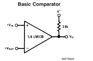
The difficulty was in reading the ABS signal from the VR sensor without upsetting the ABS control unit - my solution (which seemed quite simple at the time) was to use a 741 op-amp as a comparator, like this:

What's difficult about reading the VR sensor is that it isn't actually earthed as far as I can see - the two wires coming off it are either end of a detector coil, so have to remain independent from the vehicle (and Arduino) earth to avoid upsetting the ABS control unit. Using a comparator, I thought, would get around this, as the op-amp inputs are essentially isolated from the supply terminals and have such high input impedance, the ABS control unit should detect no change in the VR sensor circuit.
I built the circuit on strip-board as a DIY shield and wired it up...

...and was pleasantly surprised when it actually worked perfectly! That was, until two days ago, when it stopped working altogether.
I've since done quite a lot of fault-finding and have just tied myself up in knots, so if anybody can offer any advice, I'm open to any ideas whatsoever!
So far, I've confirmed that the sketch is still good and have replaced both the Arduino and the op-amp with no difference in behavior. I know the fault is in the input circuitry or the VR sensor, as the Arduino generates a calibration signal when it powers on, which drives the speedo to 100mph and this still works fine.
I've had the Arduino and shield on a workbench and found that it works exactly as expected; the comparator converts the sine-wave to a square-wave, the Arduino generates a square-wave output at 6x the input frequency and the transistor brings the 5V logic level up to 12V vehicle level.
The only unexpected (by me, at least) behavior I've discovered is that the comparator isn't changing state when the input wave crosses zero, but when it crosses 2.5V, which is half the supply Voltage - I'm using the comparator to both generate a square-wave and bring the variable VR signal level to 0-5V logic level, so it's powered via a 7805 at 0-5V. Essentially, this doesn't make any difference to the system function, though, as I still get a frequency-proportional pulse for the Arduino to read.
I've tried grounding the inverting input of the op-amp to try to improve the comparator function (i.e. force it to change state when the VR signal crosses zero), but this stops the ABS system from working, as the ABS control unit throws an error and the dashboard warning light comes on. I've tested the VR sensor and it still works as expected - without the non-inverting terminal grounded, the ABS light goes out.
What I don't understand is why it worked for a fortnight and then stopped working...I didn't change anything! Nothing's moved or broken on the shield and the Arduino is working fine. The only thing I've not changed is the VR sensor, but I've connected it to a scope and it seems to be working fine.
Any ideas? I'm properly stumped now ![]()

